Laser device and exposure method

a laser device and exposure method technology, applied in the direction of instruments, photomechanical devices, optical resonator shape and construction, etc., can solve the problems of increased cost, complicated maintenance, and increased difficulty in compensating chromatic aberration, and achieve the effect of high conversion efficiency, high degree of freedom in optical-material selection, and maximum overlapped portion of two beams

Inactive Publication Date: 2006-11-14
NIKON CORP
View PDF19 Cites 56 Cited by
  • Summary
  • Abstract
  • Description
  • Claims
  • Application Information

AI Technical Summary

Benefits of technology

[0033]For example, in a case where a fourth-order harmonic wave output is shaped using an optical system having different magnifications in the longitudinal and transverse directions, the beams of the fourth-order harmonic wave and the third-order harmonic wave need to be overlapped with each other in the subsequent seventh-order harmonic wave generation. Beam-overlapping for two luminous fluxes requires that the positions of individual beams in a bundle are matched, and the beams are satisfactorily overlapped with each other. When the fourth-order harmonic wave is shaped using the optical system having different magnifications in the longitudinal and transverse directions, also the overall shape of the bundle itself is deformed according to magnifications corresponding to the magnifications in the longitudinal and transverse directions of the lens systems being used. On the other hand, since the shape of the bundle of the third-order harmonic wave and the individual beam shapes are different from that of the fourth-order harmonic wave, the two need to be simultaneously tuned. As such, the magnification of the optical system for shaping the bundle and the magnification of the optical system for shaping the individual beam need to be set independently of each other. Because of the above, an anisotropic optical system having different magnifications depending on the longitudinal and transverse directions of each of the beams is concurrently used in addition to an ordinary cylindrical-lens pair or a combination of a lens and a cylindrical lens. Thereby, the ratio of an overlapped portion of the two beams is maximized, and high conversion efficiency can be obtained. Usable examples of the anisotropic optical system include a cylindrical-lens array, a prism array, and a DOE (diffractive optical element) in which fine diffraction gratings are distributed in a predetermined arrangement.
[0034]The anisotropic optical system is preferably inserted either on the optical path of the fundamental wave in the wavelength range of from an infrared region and a visible region or on an optical path of a harmonic wave of a low order (such as a third or fourth order). These wavelengths offer a high degree of freedom in optical-material selection, thereby enabling appropriate optical materials to be selectable.
[0035]Furthermore, in the present invention, the laser beam can be modulated by a light modulator and the like at a high frequency of, for example, about 100 kHz. As such, in comparison to a case where an excimer laser light (having a wavelength of several kHz) is used, the pulse energy can be reduced to about 1 / 1000 to 1 / 10000 to obtain the same illuminance. Therefore, when the above-described laser device is used as an exposure light source, transmittance variations due to, for example, compaction, can substantially be eliminated, and stable and high-accuracy exposure can be implemented.

Problems solved by technology

Second, when the exposure light is ultraviolet light having a wavelength of 300 nm or shorter, an optical material which can be used for a reflector member (lens) of a projection optical system is limited, and hence the difficulty increases for compensation of the chromatic aberration.
This arises various problems.
For example, the transmittance of an optical component tends to vary because of so-called compaction and the like, complicated maintenance is required and costs are increased.
In this connection, these methods arises other problems.
For example, the aforementioned adjustment requires a sensitive arrangement; and in proportion to the increase in the constituent laser elements, the complexity of the configuration needs to be increased to cause the overall devices to oscillate with the same wavelength.
However, the method has problems in that it requires an optical system for separating the seed light into the individual laser elements and an oscillatory-wavelength tuning control section, thereby increase complexity of the configuration.
In addition, the array laser as described above enables the overall device to be significantly smaller than that with the conventional excimer laser, it still causes difficulty in packaging so as to reduce the diameter of overall arrayed output beams to several centimeters or smaller.
The array laser thus configured has additional problems.
For example, each of the arrays requires the wavelength conversion section, thereby increasing the cost.
In addition, suppose misalignment has occurred in a part of the laser elements constituting the array, or damage has occurred with the constituent optical elements.

Method used


Image

  • Laser device and exposure method
  • Laser device and exposure method
  • Laser device and exposure method

Examples


Embodiment Construction

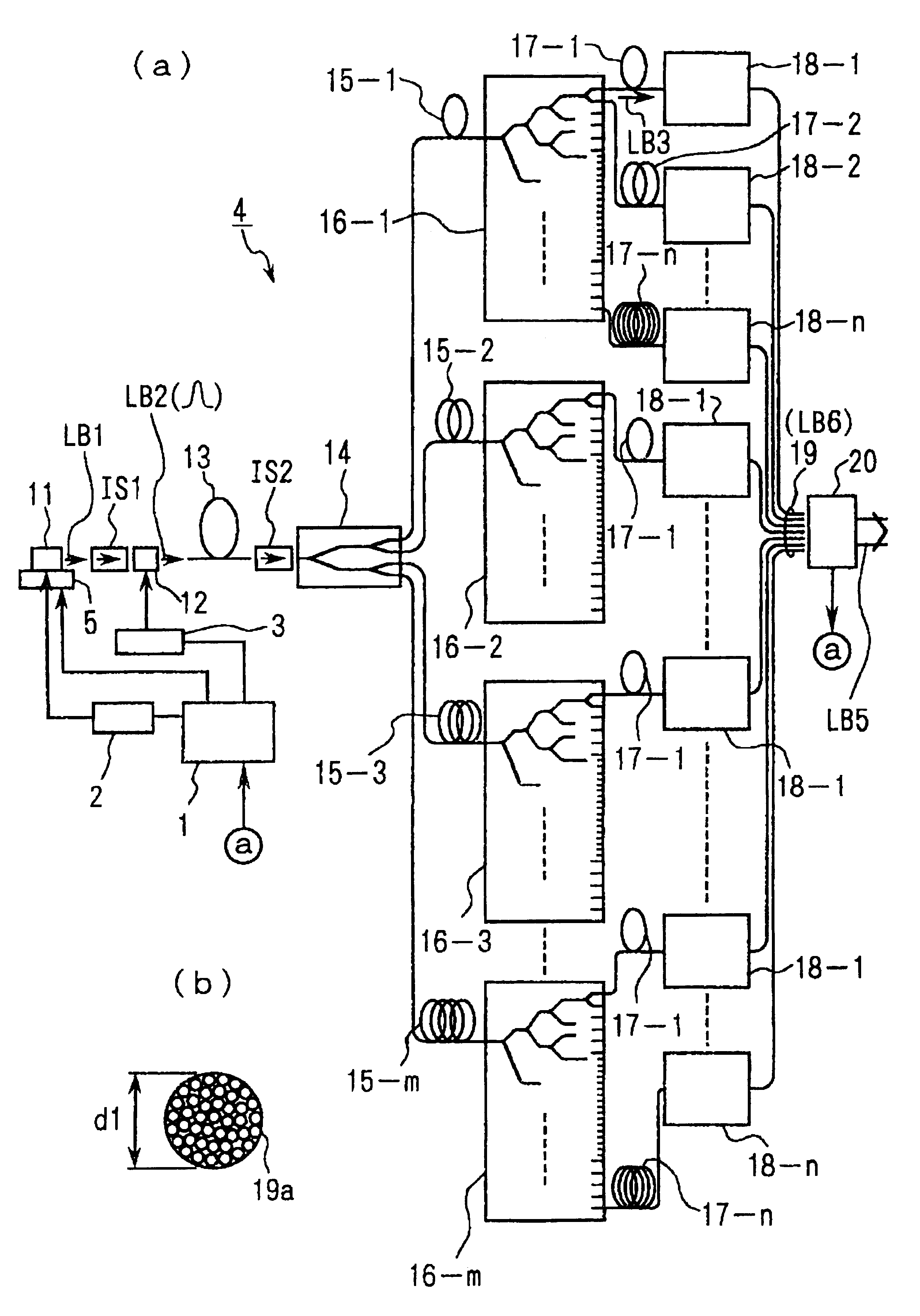
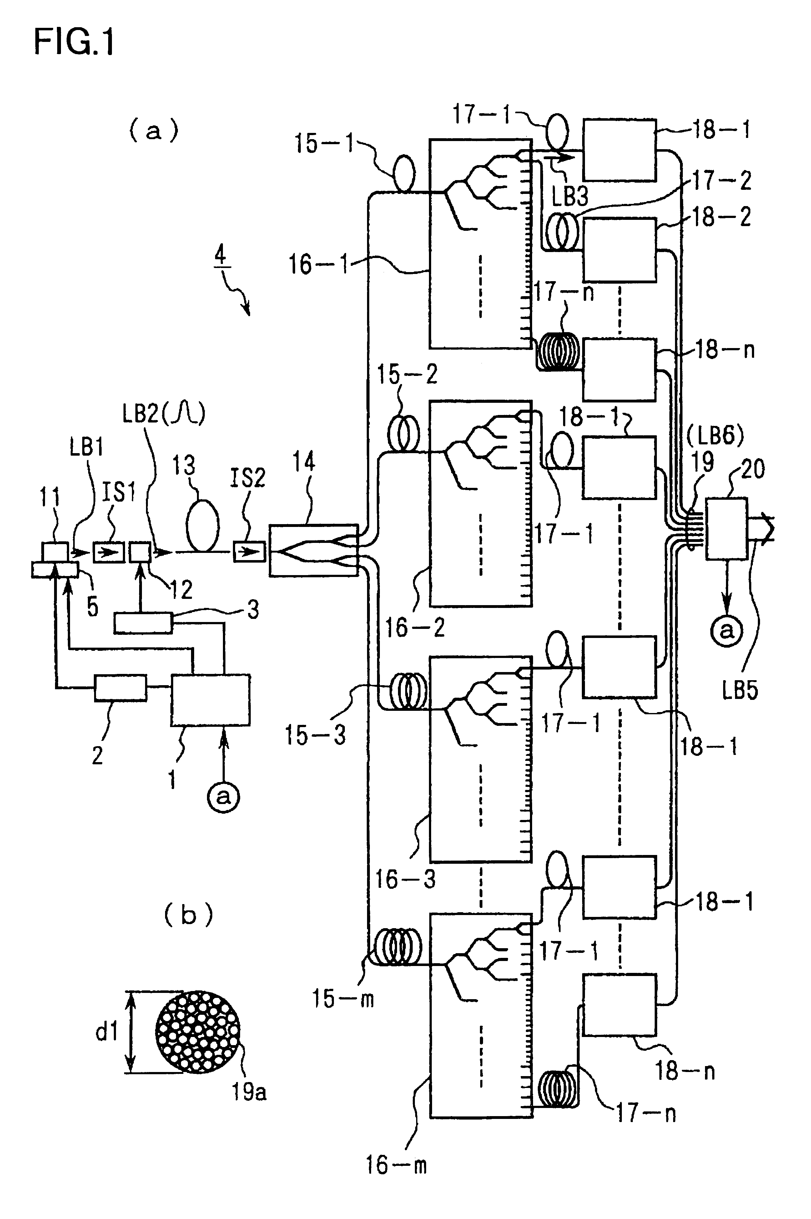
[0049]Hereinbelow, an example of a preferred embodiment according to the present invention will be described with reference to the accompanying drawings. The present example represents a configuration in which a laser device of the present invention is applied to an ultraviolet light generator that can be used as an ultraviolet-region exposure light source of a projection exposure apparatus such as a stepper or as a light source for alignment and various tests.

[0050]FIG. 1A shows an ultraviolet light generator according to the present example. Referring to FIG. 1A, a mono-wavelength oscillatory laser 11, which is provided as a laser generator section, generates a laser beam LB I that is formed of, a continuous wave (CW) having a narrow spectral width and that has a wavelength of 1.544 μm. The laser beam LB1 is incident on an optical modulating device 12, which is provided as an optical modulator, via an isolator IS1 provided for blocking reverse light. The laser beam LB1 is converte...


PUM

PropertyMeasurementUnit
wavelengthaaaaaaaaaa

Abstract

A laser device which can be used as a light source for an exposure device, can be downsized, and is easy to maintain. A laser beam (LB6) emitted from a DFB (Distributed feedback) semiconductor laser, for example, and amplified by an optical fiber amplifier is passed through non-linear optical crystals (502, 503, 504) to be sequentially doubled in frequency to thereby generate an ultraviolet-region laser beam (LB5) consisting of an octuple wave. A GdYCOB, that is, GdxY1−xCa4O(BO3)3 crystal (0≦×≦1) is used for the non-linear optical crystal (503) for a double wave-to-quadruple wave conversion, and a KAB, that is, K2Al2B4O7 crystal for the non-linear optical crystal (504) for a quadruple wave-to-octuple wave conversion. The non-linear optical crystals (502-504) are all fine-tuned in phase match angle by temperature controllers (521-523) respectively.

Description

[0001]This application is the international phase under 35 U.S.C. 371 of prior PCT International Application No. PCT / JP00 / 06131 which has an International filing date of Sep. 8, 2000 which designated the United States of America, the entire contents of which are hereby incorporated by reference.TECHNICAL FIELD[0002]The present invention relates to a laser device that generates ultraviolet light and an exposure method using this device. More specifically, the present invention is preferably used as, for example, an exposure light source or a measuring light source of an exposure apparatus used in a photolithography process for manufacturing microdevices, such as semiconductor devices, image pickup devices (such as CCDs), liquid crystal display devices, plasma display devices, and thin-film magnetic heads.BACKGROUND ART[0003]For example, an exposure apparatus used in a photolithography process for manufacturing a semiconductor integrated circuit optically reduces and projectively expo...

Claims


Application Information

Patent Timeline
Patent Type & Authority Patents(United States)
IPC IPC(8): H01S3/10G02F1/37G03F7/20
CPCG02F1/37G03F7/70025
Inventor OHTSUKI, TOMOKO
Owner NIKON CORP
Why Eureka
Try Eureka