
Containers and methods for containing pressurized fluids using reinforced fibers and methods for making such containers

a technology of reinforced fibers and containers, applied in the field of containers, can solve the problems of low cargo-carrying capacity performance factor (pf), meaningless use of steels in the plant, and high weight of steel containers, and achieves improved creep performance, good composite compaction, and higher resin fraction

Inactive Publication Date: 2006-12-12
EXXONMOBIL UPSTREAM RES CO
View PDF66 Cites 50 Cited by
  • Summary
  • Abstract
  • Description
  • Claims
  • Application Information

AI Technical Summary

Benefits of technology

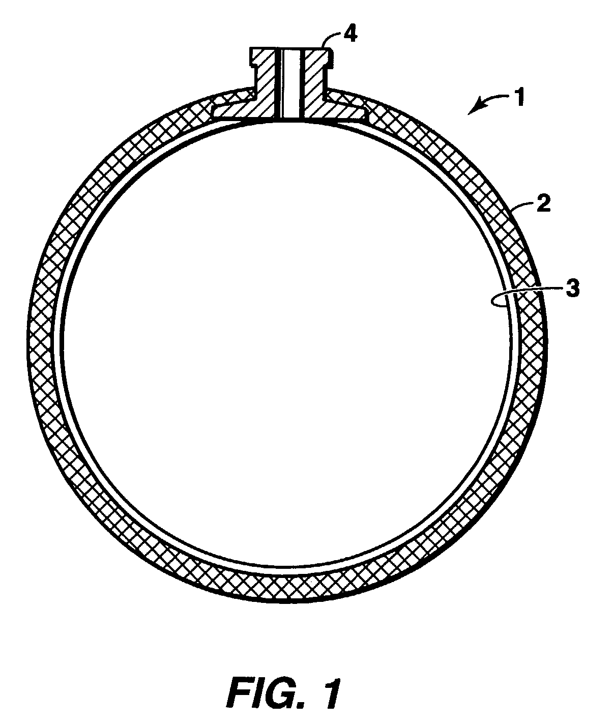
[0023]In another embodiment, the self-supporting liner is designed to withstand the critical buckling loads for the application. Consequently, the interface between the metallic liner and the composite overwrap is left unbonded. This differs from conventional lined composite container designs in which the non-load bearing liner is bonded to the composite overwrap with an adhesive that can withstand the interface shear associated with the application; this is done to mitigate against liner failure by preventing liner separation from the composite overwrap.
[0024]In yet another embodiment, the outermost overwrap layer consists essentially of carbon fibers for improved creep performance, or a material that provides similar creep performance as carbon fibers would provide. An intermediate layer of predominantly glass fiber is placed between the outermost carbon fiber overwrap and liner made of aluminum capable of cryogenic service. The autofrettage process is used to provide a residual compressive pre-stress in the liner to a degree that offsets the differential thermal contraction of the system. Without the intermediate layer of glass fiber, the residual compressive pre-stress would be inadequate to offset the much higher differential contraction between the aluminum and the carbon. The following data for a spherical pressure vessel design using aluminum 5083-0, illustrates the point. An interface bearing pressure of 34 kPa (5 psi) in tension is developed at the girth between the aluminum and the carbon fiber composite when the pressure vessel is cooled to −95° C. (−140° F.). This results after an autofrettage pressure of 5.78 MPa (850 psig), followed by a proof pressure of 5.1 MPa (750 psig) both at room temperature. The corresponding bearing pressure after rebound from proof pressure is 340 kPa (50 psig) in compression. The glass ensures positive bearing pressure at the interface thereby preventing bondline fissuring. The low yield strength of aluminum limits the residual compressive pre-stress induced in the liner after the autofrettage process.
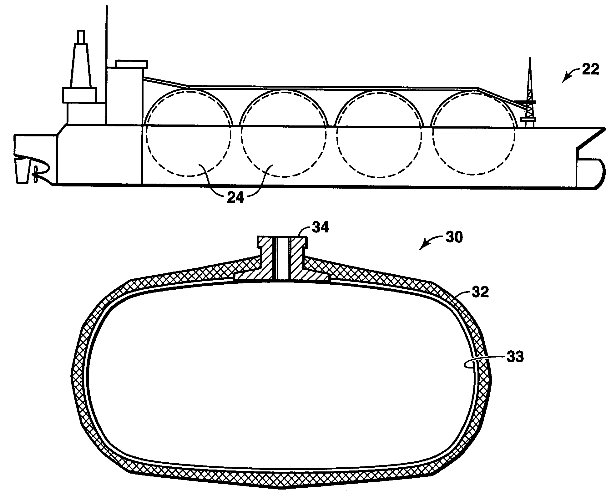
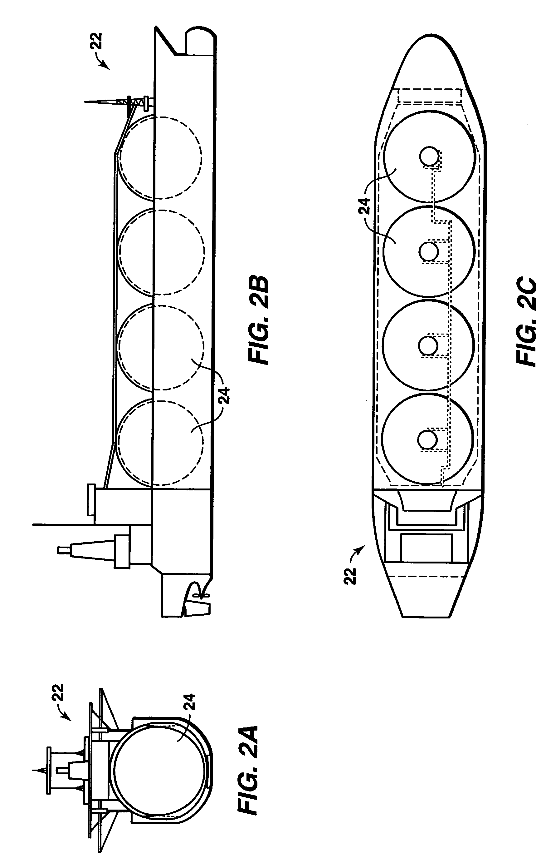
[0026]The proposed design has several advantages over the conventional PLNG containment system based on steel including the following: (i) The fabrication process is simplified; (ii) The containment system weight is reduced which favorably impacts the transport ship design; (iii) The product piping requirements are tremendously simplified; (iv) The off-loading scheme is also simplified; and (v) The insulation requirement is reduced.

Problems solved by technology

If use of the steels for constructing the containers did not provide a commercially viable means for storing and transporting the PLNG on marine vessels, then any use of the steels in the plant would be meaningless since there would be no mechanism for commercially transporting the PLNG produced by the plant.
Additionally, while use of the steels in the PLNG transportation system is commercially viable and does generate some economic savings over conventional LNG operations, the weight of the steel containers is high compared to that of its PLNG cargo, resulting in a relatively low cargo-carrying capacity performance factor (PF).
This generally limits the cycle life of the liner and hence of the pressure vessel.
Use of such composite-overwrapped pressure vessels in cryogenic service introduces another problem inherent in the design due to the difference in the CTE, or coefficient of thermal expansion or contraction, of the liner material and the composite.
um. As a typical composite pressure vessel is cooled to cryogenic temperatures, the liner, which is typically aluminum, tends to contract more than the composite material causing the liner to separate from the windings and subsequently causing pre-mature fail
However, the load-bearing, inner wall of Bolton's vessel is designed for a maximum pressure of approximately 0.34 to 0.41 MPa (50 to 60 psi) and, thus, Bolton's vessel is not suitable for transport and storage of PLNG.
Stiffening frames are therefore required for buckling resistance, which adds to the complexity of the design and limits the size of the pressure vessel.
However, the complexity and hence high cost of the metal deposition process and the liner fabrication process make the tanks / vessels of Bees et al. and Mitlitsky et al. suitable primarily for applications where maximized payload-carrying capacity is the primary objective and, thus, low tank / vessel weight is of very high premium.
However, none of the containers discussed in these publications are designed for containing fluids that are at both temperatures less than −40° C.
The service pressure for these spherical tanks is too low for PLNG application.
Designing very large tanks for the PLNG service pressure using conventional materials presents fabrication challenges due to the unusually large material thicknesses required.
However, in spite of the high strength of the steels used in the construction of the PLNG containers described in the PLNG Patent, the weight of a containment system using these containers will be high relative to the cargo and will constrain the ship design through parameters such as draft and stability.
Furthermore, the arrangement of the cylindrical containers will likely affect the geometric design of the ship affecting the ship block coefficient and hence increasing the power requirement, and obstructing the line-of-sight from the engine room.
However, the fabrication complexity of thin-lined composite containers limits the size and geometry of the containers and thereby increases the complexity of piping requirements and impact on geometric design of the ship.

Method used


Image

  • Containers and methods for containing pressurized fluids using reinforced fibers and methods for making such containers
  • Containers and methods for containing pressurized fluids using reinforced fibers and methods for making such containers
  • Containers and methods for containing pressurized fluids using reinforced fibers and methods for making such containers

Examples


Embodiment Construction

Composite Overwrap

[0042]The composite overwrap in a container according to this invention preferably provides the primary structural support for the operating loads. The composite overwrap is preferably a material system comprising high-performance fibers in a resin matrix capable of cryogenic temperature service. As used herein “cryogenic temperature” means any temperature of about −62° C. (−80° F.) and colder. An example of such a resin is the CTD 525 epoxy cryogenic resin. Two classes of material systems have been designed for this invention.

[0043]The first class of material systems comprises: (i) a high performance fiber, preferably selected from the following fibers (carbon, glass, kevlar®, aramid, UHMWP); and (ii) a thermo-setting resin (such as the CTD-525 epoxy cryogenic resin). One embodiment uses high-performance carbon fiber such as TORAY T-700, GRAFIL 34-600 or ZOLTEK PANEX 35 for better creep performance. This first class of material system is characterized by a constan...


PUM

PropertyMeasurementUnit
temperatureaaaaaaaaaa
pressureaaaaaaaaaa
temperaturesaaaaaaaaaa

Abstract

Containers suitable for storing pressurized fluids at cryogenic temperatures of −62° C. (−80° F.) and colder are provided and comprise a self-supporting liner and load-bearing composite overwrap, whereby means are provided for substantially preventing failure of the container during temperature changes.

Description

[0001]This application claims the benefit of U.S. Provisional Application No. 60 / 367824, filed Mar. 27, 2002.FIELD OF THE INVENTION[0002]The present invention relates to improved containers and methods for containing pressurized fluids and to methods for making such containers. More particularly, the present invention relates to containers comprising a self-supporting liner and a load-bearing composite overwrap, whereby means are provided for substantially preventing container failure during changes in temperature between ambient and about −123° C. (−190° F.), and to methods for containing pressurized fluids using such containers and to methods of making such containers. In some embodiments, the present invention relates to improved containers and methods for storing pressurized liquefied natural gas (PLNG).BACKGROUND OF THE INVENTION[0003]Various terms are defined in the following specification. For convenience, a Glossary of terms is provided herein, immediately preceding the clai...

Claims


Application Information

Patent Timeline
Patent Type & Authority Patents(United States)
IPC IPC(8): F17C1/12B63B25/14B63B25/16F17C1/14F17C1/00F17C13/00
CPCF17C1/002F17C2201/0109F17C2201/0123F17C2201/0128F17C2201/035F17C2201/052F17C2201/054F17C2203/0604F17C2203/0607F17C2203/0619F17C2203/0621F17C2203/0639F17C2203/0646F17C2203/0648F17C2203/0651F17C2203/066F17C2203/0663F17C2203/0673F17C2205/018F17C2205/0305F17C2209/221F17C2209/232F17C2221/033F17C2223/0161F17C2223/033F17C2223/035F17C2260/012F17C2260/013F17C2270/0105Y02E60/32
Inventor MINTA, MOSESBOWEN, RONALD R.
Owner EXXONMOBIL UPSTREAM RES CO
Learn More