Methanol manufacture using pressure swing reforming

a technology of methanol and reforming, which is applied in the field of methanol manufacture, can solve the problems of high heat generation, low productivity, and high cost of synthesis, and achieve the effect of facilitating the production of high pressure synthesis gas

Active Publication Date: 2006-12-12
EXXONMOBIL CHEM PAT INC
View PDF16 Cites 77 Cited by
  • Summary
  • Abstract
  • Description
  • Claims
  • Application Information

AI Technical Summary

Benefits of technology

[0024]In one embodiment of the above process, the reforming stage is conducted at a higher pressure than the regeneration stage, thereby creating a pressure swing and facilitating the production of high pressure synthesis gas. Conveniently, the reforming stage is conducted at a pressure of about 1000 kPa to about 10,000 kPa, such as about 2000 kPa to about 7,500 kPa, whereas the regeneration stage is conducted at a pressure of about 100 kPa to about 2,000 kPa, such as about 200 kPa to about 1500 kPa.

Problems solved by technology

The associated costs of producing the synthesis gas currently account for over half of the capital investment in the methanol plant.
Unfortunately, steam reforming furnaces occupy a very large volume of space, orders of magnitude greater than the tube volume, such that low productivity limits the economic attractiveness of the process.
However, gas-phase reaction kinetics tend to over-oxidize some of the feed, resulting in excessive heat generation and substantial yield of H2O, CO2, and unreacted hydrocarbons that may leave the reactor as soot.
However, autothermal reforming requires a source of oxygen.
In refinery or chemicals embodiments, this oxygen is typically provided as purified O2, but the cost of air separation can be greater than the cost of the autothermal reforming process.
However, the examples and commercial projections within these patents describe a process that operates at very low productivity, with space velocities of around 95 hr−1 (as C1-equivalent).

Method used


Image

  • Methanol manufacture using pressure swing reforming
  • Methanol manufacture using pressure swing reforming
  • Methanol manufacture using pressure swing reforming

Examples


example 1

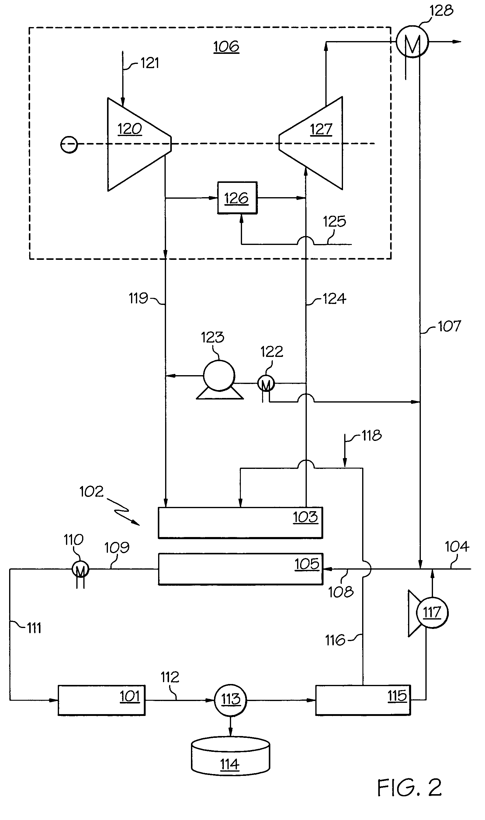
[0112]This Example provides a computer simulation of the integrated process shown in FIG. 2 using a General Electric Frame 9E Gas Turbine as the turbine 106 and assuming additional fuel is consumed in the burner 126 to provide a heat value flow to the turbine of 629 MBTU / hr. Heat values, as used herein, represent stream heat of combustion, on a lower heating value basis.

[0113]The pressure swing reformer 102 is operated as a pair of reactors, each alternating between 15 seconds in the regenerating stage 103 and 15 seconds in the reforming stage 105. Reforming and recuperation zones include a packing comprising a 1200 cell / in2 (186 cell / cm2) honeycomb monolith having a wall thickness of 7 mil (0.18 mm), a wetted area of 41 cm−1 and a bulk volumetric heat capacity of 0.23 cal / cc° C. The reforming zone comprises two thirds of the total bed, and comprises a rhodium catalyst supported on the honeycomb monolith. The space velocity during reforming stage, on a C1 hydrocarbon basis, is 4000 ...

example 2

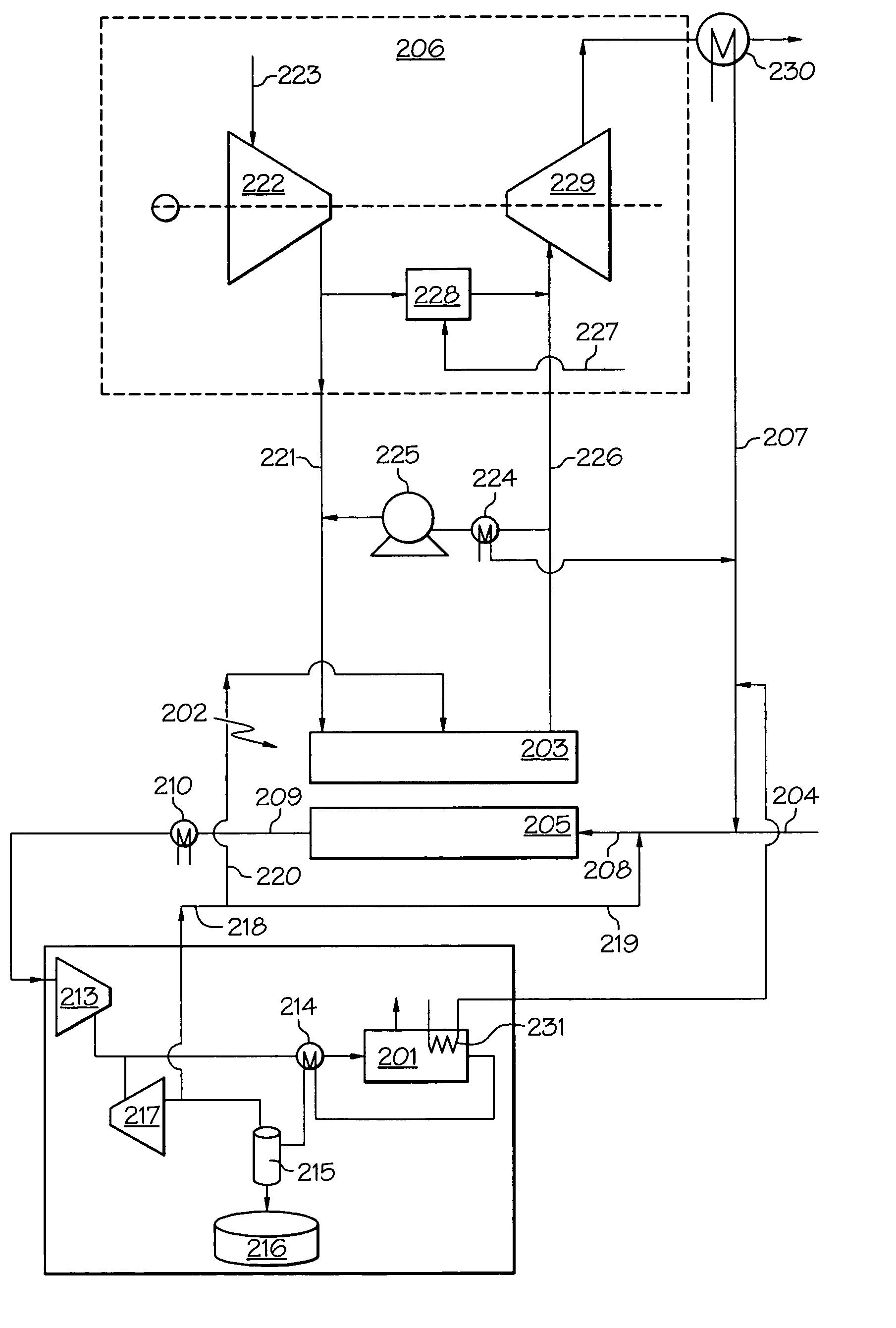
[0120]This Example provides a computer simulation of the integrated process shown in FIG. 3 using a General Electric Frame 9E Gas Turbine as the turbine 206 and assuming additional fuel is consumed in the burner 227 to provide a heat value flow to the turbine of 923 MBTU / hr.

[0121]The pressure swing reformer 202 is operated as a pair of reactors, each alternating between 15 seconds in regenerating stage 203 and 15 seconds in reforming stage 205. Reforming and recuperation zones include a packing comprising a 1200 cell / in2 (186 cell / cm2) honeycomb monolith having a wall thickness of 7 mil (0.18 mm), a wetted area of 41 cm−1 and a bulk volumetric heat capacity of 0.23 cal / cc° C. The reforming zone comprises two thirds of the total bed, and comprises a rhodium catalyst supported on the honeycomb monolith. The space velocity during the reforming stage, on a C1 hydrocarbon basis, is 5000 hr−1.

[0122]Methane is fed through line 204 to the reforming stage 205 at a rate of 14,309 kgmole / hr an...

example 3

[0128]This Example provides a computer simulation of the integrated process shown in FIG. 4 using a General Electric Frame 9E Gas Turbine as the turbine 206 and assuming additional fuel is consumed in the burner 227 to provide a heat value flow to the turbine of 923 MBTU / hr.

[0129]The pressure swing reformer 202 is operated as a pair of reactors, each alternating between 15 seconds in regenerating stage 203 and 15 seconds in reforming stage 205. Reforming and recuperation zones include a packing comprising a 1200 cell / in2 (186 cell / cm2) honeycomb monolith having a wall thickness of 7 mil (0.18 mm), a wetted area of 41 cm−1 and a bulk volumetric heat capacity of 0.23 cal / cc° C. The reforming zone comprises two thirds of the total bed, and comprises a rhodium catalyst supported on the honeycomb monolith. The space velocity during the reforming stage, on a C1 hydrocarbon basis, is 5000 hr−1.

[0130]Methane is fed through line 204 to the reforming stage 205 at a rate of 14,309 kgmole / hr an...


PUM

PropertyMeasurementUnit
pressureaaaaaaaaaa
pressureaaaaaaaaaa
pressureaaaaaaaaaa

Abstract

A process for producing methanol is described in which a hydrocarbon is steam reformed in a reforming zone, and during the reforming stage, of a cyclic steam reformer having a reforming stage and a regeneration stage, the steam reforming being conducted under conditions effective to produce a first effluent stream containing synthesis gas. Fuel and an oxygen-containing gas are combusted in the regeneration stage of the reformer so as to reheat the reforming zone to a temperature sufficient for the reforming stage and generate a flue gas. At least part of the first effluent stream is contacted with a methanol synthesis catalyst under conditions effective to convert synthesis gas to methanol and form a methanol-containing stream and a tail gas stream comprising unreacted carbon monoxide and hydrogen. At least part of the tail gas stream is recycled as fuel for the regeneration stage of the cyclic steam reformer.

Description

CROSS REFERENCE TO RELATED APPLICATIONS[0001]This application is a continuation-in-part of U.S. application Ser. No. 10 / 738,782, filed Dec. 17, 2003.FIELD OF INVENTION[0002]The present invention relates broadly to the manufacture of methanol. More particularly the invention relates to a process for making methanol that integrates pressure swing reforming to convert a hydrocarbon, such as methane, to synthesis gas with conversion of the synthesis gas to methanol.BACKGROUND OF INVENTION[0003]Methanol is a major chemical raw material. Present global methanol consumption is about 27 million tons per year. Major uses of methanol include the production of acetic acid, formaldehyde, and methy-t-butylether. The latter, an oxygenate additive to gasoline, accounts for about a third of all use. Worldwide demand for methanol is expected to increase as much as five fold over the next decade as potential new applications become commercialized. Such applications include the conversion of methanol ...

Claims


Application Information

Patent Timeline
Patent Type & Authority Patents(United States)
IPC IPC(8): C07C27/00C07C1/00C07C1/24C07C29/151
CPCC07C29/1518C07C31/04C07C31/08C07C31/10C07C31/02Y02P30/20Y02P30/40
Inventor HERSHKOWITZ, FRANKLATTNER, JAMES R.
Owner EXXONMOBIL CHEM PAT INC
Why Eureka
Try Eureka