Spectrometer incorporating signal matched filtering

Active Publication Date: 2006-12-26
ADAMS BRUCE WILLIAM MR
View PDF8 Cites 33 Cited by
  • Summary
  • Abstract
  • Description
  • Claims
  • Application Information

AI Technical Summary

Benefits of technology

[0006]An object of the present invention is to provide a spectrometer incorporating signal matched filtering. In accordance with an aspect of the present invention, there is provided an optical system for performing a spectral analysis of test samples comprising: a photonic energy source for emitting electromagnetic radiation, wherein said photonic energy source is controlled by a digital signal processing means; an optical emission processing means for receiving electromagnetic radiation from the photonic energy source and transmitting one or more illumination wavelengths to a test sample, wherein the optical emission processing means is controlled by the digital signal processing means; a received light optical processing means for collecting and isolating one or more wavelengths of received electromagnetic radiation from the test sample and transmitting the isolated one or more wavelengths of received electromagnetic radiation to an optical detector, wherein said received light optical processing means is controlled by the digital signal processing means; an optical detector for sensing and converting the isolated one or more wavelengths of received electromagnetic radiation into an electrical signal; and digital signal processing means for performing matched filtering of the electrical

Problems solved by technology

However, the determination of the reference signal at the time of scanning of the test sample is critical to

Method used


Image

  • Spectrometer incorporating signal matched filtering
  • Spectrometer incorporating signal matched filtering
  • Spectrometer incorporating signal matched filtering

Examples


example i

Optical System for Analyzing Fluid Samples

[0122]In one embodiment of the present invention, the optical system can be designed to perform the analysis of fluid samples, for example for the detection of turbidity and / or bio-mass in a flowing water sample. This form of the invention may also be used for the analysis of a petroleum sample, for example. In this embodiment of the optical system the change(s) in the spectral properties of a test sample are detected and evaluated.

[0123]An embodiment of the invention a system used for this purpose is illustrated in FIG. 16. This example is directed towards water analysis, however it may equally well be used for the analysis of other fluids. The optical system comprises a digital signal processor 600, a LED control system 610, an illumination system 620, a sample chamber or water flow 630 into which the optical probe 700 may be placed, detector optics 640, a photodetector 650, photodetector electronics 660 and a network 670 to which the DSP ...

example ii

Spectrometer Incorporating a Matched Filter Receiver

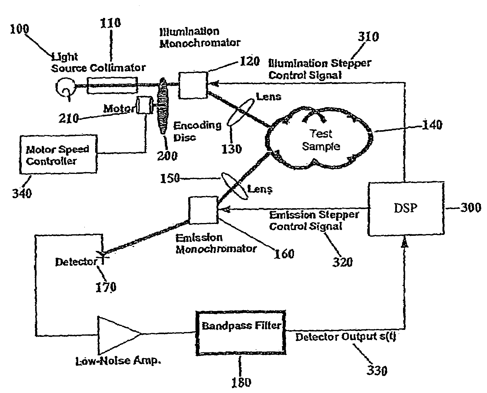
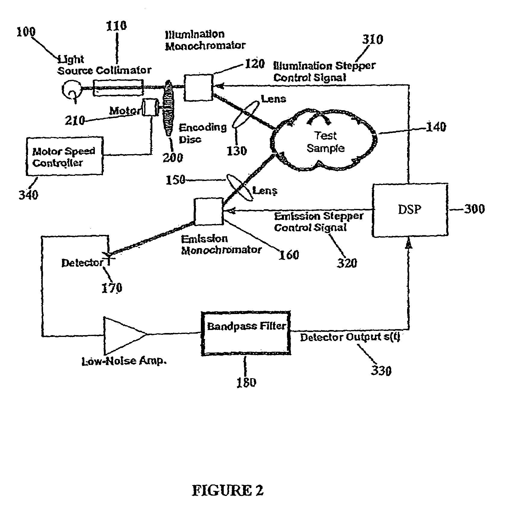
[0131]One embodiment is shown in FIG. 14 comprising a light source, for example, a miniature Xenon bulb that has an emission spectrum approximately equal to that of a 6000° K Blackbody with a few discrete spectral lines. The light is collimated and modulated by a chopper wheel, which provides a 500 Hz On-Off modulation to the light entering the illumination monochromator. The illumination monochromator operating under the control of the CPU sweeps the illumination wavelength from 250 nm to 800 nm in steps of 10 nm. This illumination is focused onto the area of interest. The received light monochromator operating under the control of the CPU sweeps the received light wavelength from 250 nm to 800 nm in steps of 10 nm. It is controlled in such a way that for every illumination wavelength sample λi, it sweeps over the range of wavelengths greater than or equal to λi. A Ga-As photodiode is used as the optical detector, with the signal ...

example iii

[0134]One embodiment of this invention comprises an optical system comprises: a) a light emitting diode (LED), as the illumination light source, which is controlled by the digital signal processing means to emit a radiation bandwidth ranging from 380 to 500 nanometers; b) a stepper motor controlled, grating illumination monochromator which is controlled by the digital signal processing means to receive light from the illumination device and to deliver the Nth wavelength in a pulse sequence; c) an optical fibre probe that is coupled to the monochromator with collimating and focusing elements that delivers the Nth wavelength to a subject area. This optical probe is located in an assembly that orients the illumination optics with that of the detecting optics such that they are at a constant angle to each other; d) collecting means for gathering the resultant radiation of the Nth wavelength and delivering the information via light collection lenses and fibre coupled to a stepper motor c...


PUM


Abstract

An optical system for performing a spectral analysis of test samples is provided. The optical system comprises a photonic energy source, an optical emission processing system, a received light optical processing system, an optical detector and a digital signal processing system. The optical emission processing system transmits one or more illumination wavelengths to a test sample. The received light optical processing system collects and isolates one or more wavelengths received from the test sample and transmits them to an optical detector. The optical detector converts the isolated one or more wavelengths of received electromagnetic radiation into an electrical signal which is transmitted to the digital signal processing system. The digital signal processing system performs matched filtering of the electrical signal received from the optical detector and additionally controls the functionality of the photonic energy source, the optical emission processing system and the received light optical processing system.

Description

FIELD OF THE INVENTION[0001]This invention relates to the field of optical detectors, in particular with regard to spectrometers.BACKGROUND OF THE INVENTION[0002]The are a number of spectrophotometers or spectrometers that are used to detect the spectral characteristics of a test sample. For example, U.S. Pat. No. 4,330,207 discloses a fluorescence spectrophotometer comprising a light source, an excitation side monochromator which makes light from the light source be subjected to spectroscopic analysis for illuminating as actinic light a sample, a fluorescence side monochromator which makes fluorescence light from the sample be subjected to spectroscopic analysis, a detector which detects light from the fluorescence side monochromator, and a scanning means which adjusts both the monochromators to the wavelengths of the actinic light and the fluorescence light to be scanned. These monochromators are arranged in such a way that one of them is automatically set to the location of the p...

Claims


Application Information

Patent Timeline
IPC IPC(8): G01J3/30G01N21/64G01J3/14G01J3/28G01J3/44G01N21/27
CPCG01J3/28G01J3/4406G01N21/4738G01N21/64G01N21/645G01J3/14
Inventor ADAMS, BRUCE W.MCCONNELL, PETER R. H.
Owner ADAMS BRUCE WILLIAM MR
Why Eureka
Try Eureka