Pitch-based carbon foam heat sink with phase change material

a carbon foam and heat sink technology, applied in the field of porous carbon foam filled with phase change materials, can solve the problems of insufficient heat flux of hot objects, inability to use certain applications, and insufficient heat flux for all, and achieve the effect of high thermal conductivity and rapid emitted hea

Inactive Publication Date: 2007-01-02
UT BATTELLE LLC
View PDF102 Cites 6 Cited by
  • Summary
  • Abstract
  • Description
  • Claims
  • Application Information

AI Technical Summary

Benefits of technology

[0016]An object of the present invention is production of encased high thermal conductivity porous carbon foam filled with a phase change material wherein tremendous amounts of thermal energy are stored and emitted very rapidly. The porous foam is filled with a phase change material (PCM) at a temperature close to the operating temperature of the device. As heat is added to the surface, from a heat source such as a computer chip, friction due to re-entry through the atmosphere, or radiation such as sunlight, it is transmitted rapidly and uniformly throughout the foam and then to the phase change material. As the material changes phase, it absorbs orders of magnitude more energy than non-PCM material due to transfer of the latent heat of fusion or vaporization. Conversely, the filled foam can be utilized to emit energy rapidly when placed in contact with a cold object.
[0017]Non-limiting embodiments disclosed herein are a device to rapidly thaw frozen foods or freeze thawed foods, a design to prevent overheating of satellites or store thermal energy as they experience cyclic heating during orbit, and a design to cool leading edges during hypersonic flight or re-entry from space.

Problems solved by technology

Typically these applications produce heat so rapidly that normal dissipation through cooling fins, natural convection, or radiation cannot dissipate the heat quickly enough and, thus, the object over heats.
Unfortunately, as the temperature of the heat sink rises the heat flux from the hot object decreases, due to a smaller temperature difference between the two objects.
Therefore, although this method of energy storage can absorb large quantities of heat in some applications, it is not sufficient for all applications
Although a solid block of phase change material has a very large theoretical capacity to absorb heat, the process is not a rapid one because of the difficulties of heat transfer and thus it cannot be utilized in certain applications.
If the high conductivity to foam is filled with the phase change material, the process can become very rapid.
Since most phase change materials have a low thermal conductivity, the rate of heat transfer through the material is limited, but this is offset by the high energy absorbing capability of the phase change.
Unfortunately, the liquid has a much lower thermal conductivity, thus hampering heat flow further.
In fact, the overall low thermal conductivity of the solid and liquid phase change materials limits the rate of heat absorption and, thus, reduces the efficiency of the system.
Unfortunately, carbon foams and carbon honeycomb materials are the only available materials for use in high temperature applications (>1600° C.).
High thermal conductivity carbon honeycomb materials are extremely expensive to manufacture compared to low conductivity honeycombs, therefore, a performance penalty is paid for low cost materials.
High conductivity carbon foams are also more expensive to manufacture than low conductivity carbon foams, in part, due to the starting materials.
This is a time consuming step and can be an expensive step depending on the part size and equipment required.
However, these precursors produce a “glassy” or vitreous carbon which does not exhibit graphitic structure and, thus, has low thermal conductivity and Low stiffness.
This can be an expensive step in the utilization of the foam.

Method used


Image

  • Pitch-based carbon foam heat sink with phase change material
  • Pitch-based carbon foam heat sink with phase change material
  • Pitch-based carbon foam heat sink with phase change material

Examples


example 1

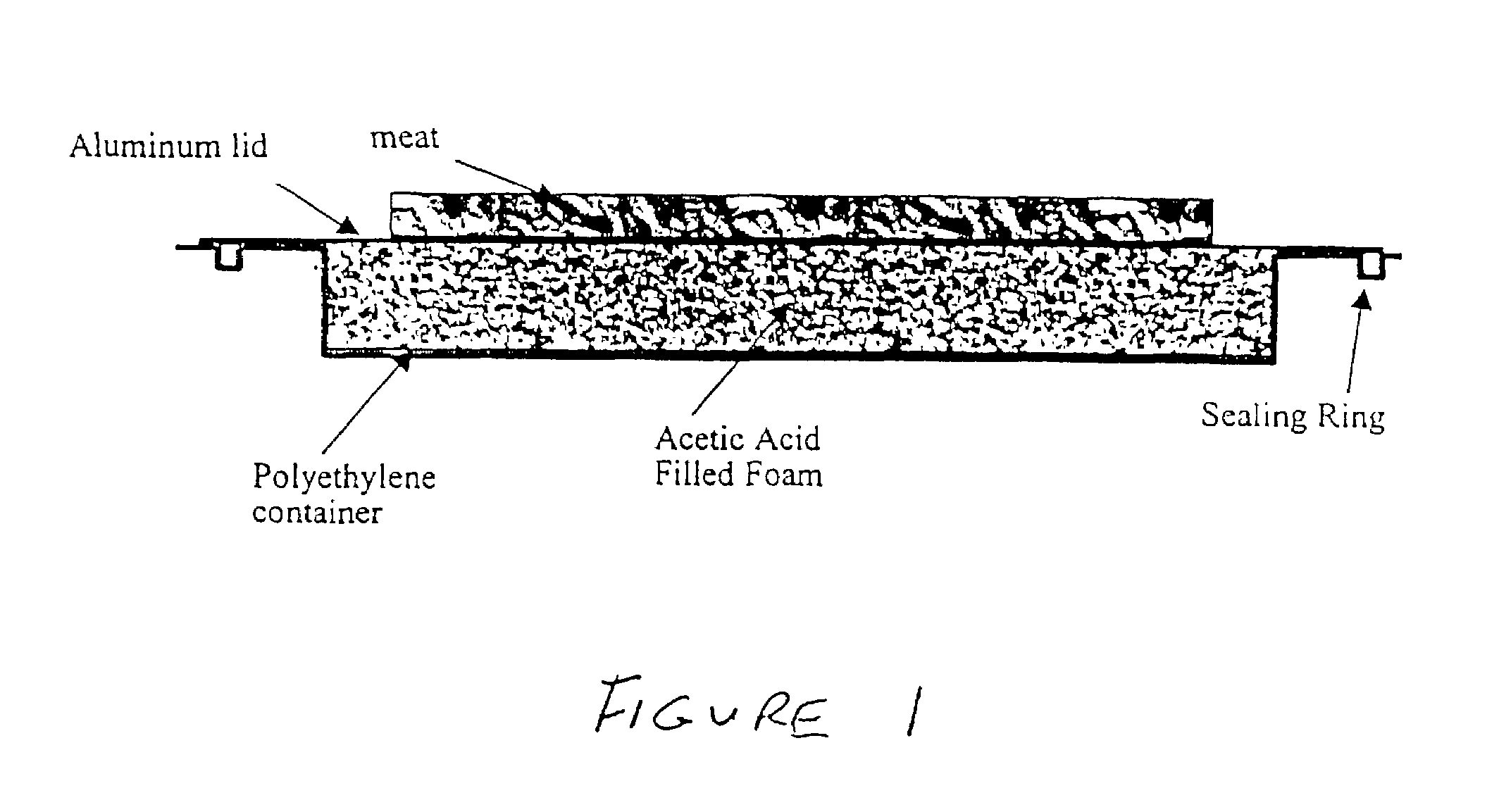
Device for Thawing Food

[0036]Acetic acid has a heat of melting of 45 J / g at a melting point of 11° C. The heat of melting of food, primarily ice, is roughly 79 J / g at 0° C. Therefore, take a block of foam and fill it with liquid acetic acid at room temp. The foam will be encased in a box made from an insulating polymer such as polyethylene on all sides except the top. The top of the foam / acetic acid block will be capped with a high thermal conductivity aluminum plate that snaps into place thus sealing the foam / acetic acid inside the polymer case (illustrated in FIG. 1). If the foam block is 10-in.×15-in.×0.5-in. thick, the mass of foam is 614 grams. The mass of acetic acid that fills the foam is roughly 921 grams. Therefore, when a piece of frozen meat is placed in contact with the top of the aluminum block, the foam will coot to the freezing point of the acetic acid (11° C.). At this point, the heat given off from the acetic acid as it freezes (it also remains at 11° C.) will be eq...

example 2

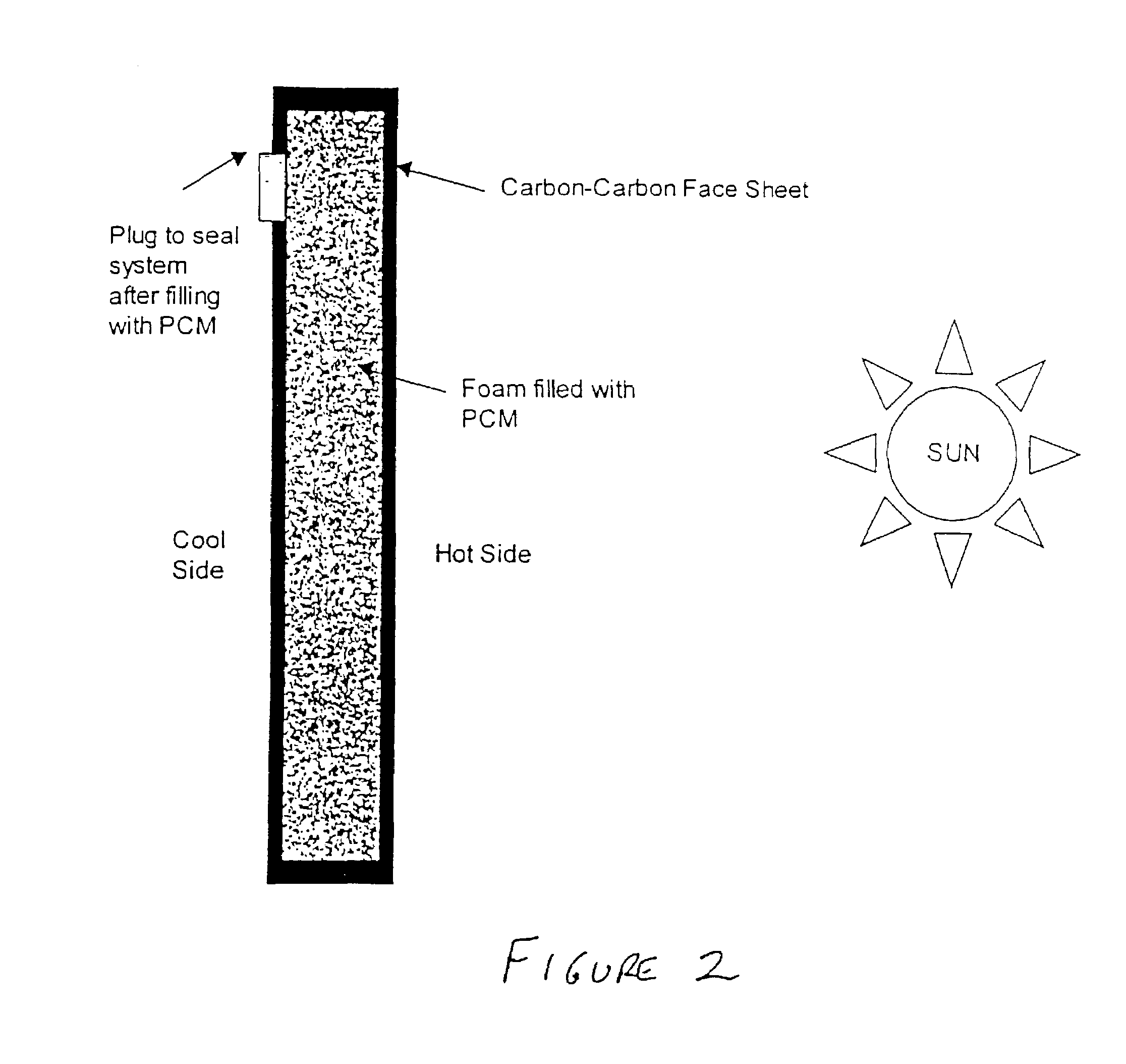
Heat Sink To Prevent Overheating of Satellites During Cyclic Orbits.

[0037]Produce a carbon-carbon composite with the foam in which the foam is a core material with carbon-carbon face sheets (FIG. 2). Fill the foam core with a suitable phase change material, such as a paraffin wax, that melts around the maximum operating temperature of the satellite components. One method to perform this would be to drill a hole in one surface of the carbon-carbon face sheets and vacuum fill the phase change material in the liquid state into the porous foam. Once filled, the sample can be cooled (the phase change material solidifies) and the hole can be plugged with an epoxy or screw-type cap. The epoxy and any other sealant must be able to withstand the operating temperature of the application. The foam-core composite will to then be mounted on the side of the satellite that is exposed to the sun during orbit. As the satellite orbits the earth and is exposed to the sun, the radiant energy from the s...

example 3

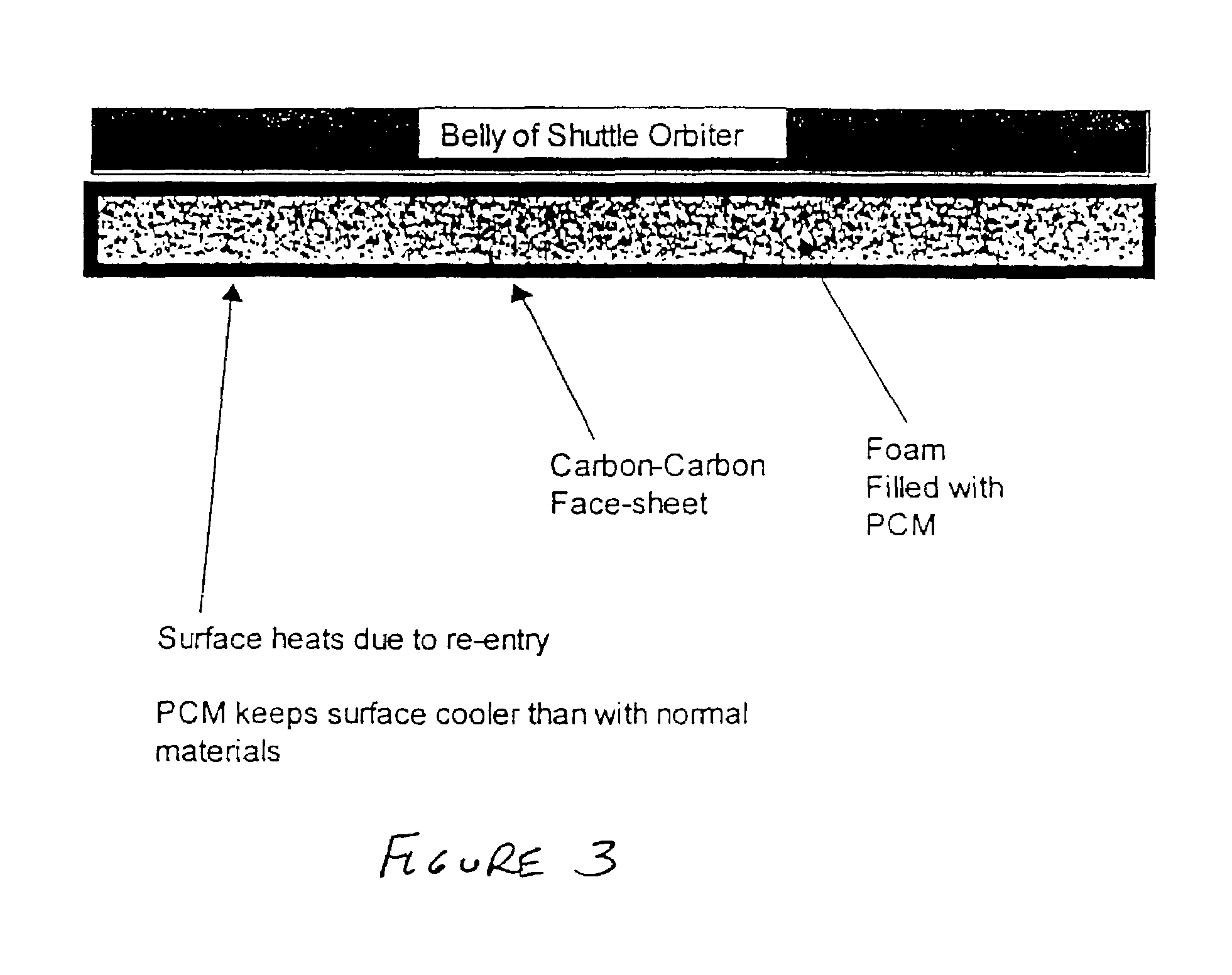
Heat Sink for Leading Edges

[0038]Currently, the shuttle orbiter experiences extreme heats during reentry. Specifically, the leading edges of the craft can reach 1800° C. and the belly of the craft can reach temperatures as high as 1200° C. If a foam core composite panel is placed at the surface of the leading edges and at the surface of the belly (FIG. 3), it would be able to absorb enough energy to dramatically reduce the maximum temperature of the hot areas. This also would permit a faster re-entry or (steeper glide slope) and maintain the current maximum temperatures. In this case the phase change material would most likely be an alloy, e.g. germanium-silicon, which melts around 800–900C. and does not vaporize until much higher than the maximum temperature of the craft.

[0039]For example, Germanium has a heat of formation (heat of melting) of 488 J / g. This would require 1.0 Kg of Germanium to reduce the temperature of 1 Kg of existing carbon / carbon heat-shield by 668° C. In other ...


PUM

PropertyMeasurementUnit
temperatureaaaaaaaaaa

Abstract

A process for producing a carbon foam heat sink is disclosed which obviates the need for conventional oxidative stabilization. The process employs mesophase or isotropic pitch and a simplified process using a single mold. The foam has a relatively uniform distribution of pore sizes and a highly aligned graphic structure in the struts. The foam material can be made into a composite which is useful in high temperature sandwich panels for both thermal and structural applications. The foam is encased and filled with a phase change material to provide a very efficient heat sink device.

Description

CROSS REFERENCE TO RELATED APPLICATIONS[0001]This application is a (1) divisional of U.S. patent application Ser. No. 09 / 489,640 filed on Jan. 24, 2000 now U.S. Pat. No. 6,780,505, which itself is a (2) continuation of U.S. patent application Ser. No. 09 / 093,406, filed on Jun. 8, 1998 now U.S. Pat. No. 6,037,032, which is itself a continuation-in-part of U.S. patent application Ser. No. 08 / 921,875 filed Sep. 2, 1997 now U.S. Pat. No. 6,033,506 and U.S. patent application Ser. No. 08 / 923,877 filed on Sep. 2, 1997 now abandoned, and (3) a continuation-in-part of U.S. patent application Ser. No. 09 / 337,027 filed Jun. 25, 1999 now U.S. Pat. No. 6,261,485, which itself is a continuation of U.S. patent application Ser. No. 08 / 921,875 filed Sep. 2, 1997, and (4) a continuation-in-part of U.S. patent application Ser. No. 09 / 136,596 filed Aug. 19, 1998 now U.S. Pat. No. 6,398,343, which itself is a divisional of U.S. patent application Ser. No. 08 / 92 1,875 filed Sep. 2, 1997.[0002]This appli...

Claims


Application Information

Patent Timeline
Patent Type & Authority Patents(United States)
IPC IPC(8): C09K5/14B32B5/18C04B38/00C09K5/06F24F5/00F28D5/00F28D20/02F28F13/00
CPCB32B5/18C04B38/00C09K5/06F24F5/0035F28D20/023F28F13/003F28D5/00Y10T428/2918Y02B30/545Y02E60/145Y10T428/249954Y02B30/54Y02E60/14Y02P20/10
Inventor KLETT, JAMES W.BURCHELL, TIMOTHY D.
Owner UT BATTELLE LLC
Why Eureka
Try Eureka