Platinum-ruthenium containing catalyst formulations for hydrogen generation

a technology of hydrogen generation and catalyst formulation, which is applied in the field of methods and catalysts to achieve the effect of increasing the selectivity of hydrogen generation, high activity and high selectivity

Active Publication Date: 2007-01-09
FREESLATE +1
View PDF52 Cites 35 Cited by
  • Summary
  • Abstract
  • Description
  • Claims
  • Application Information

AI Technical Summary

Benefits of technology

[0057]Discussion regarding the particular function of various components of catalysts and catalyst systems is provided herewith solely to explain the advantage of the invention, and is not limiting as to the scope of the invention or the intended use, function, or mechanism of the various components and / or compositions disclosed and claimed. As such, any discussion of component and / or compositional function is made, without being bound by theory and by current understanding, unless and except such requirements are expressly recited in the claims. Generally, for example, and without being bound by theory, the metals, Pt, component a), and Ru, component b), both have activity as WGS catalysts. The metals or metalloids of component c) may themselves have activity as WGS catalysts, such as Co, but function in combination with either or both of Pt and Ru to impart beneficial properties to the catalyst of the invention.
[0058]Catalysts of the invention can catalyze the WGS reaction at varying temperatures, avoid or attenuate unwanted side reactions such as methanation reactions, as well as generate a hydrogen-rich gas, such as a hydrogen-rich syngas. The composition of the WGS catalysts of the invention and their use in WGS reactions are discussed below.1. DEFINITIONS
[0059]Water gas shift (“WGS”) reaction: Reaction which produces hydrogen and carbon dioxide from water and carbon monoxide, and vice versa:
[0061]Generally, and unless explicitly stated to the contrary, each of the WGS catalysts of the invention can be advantageously applied both in connection with the forward reaction as shown above (i.e. for the production of H2), or alternatively, in connection with the reverse reaction as shown above (i.e., for the production of CO). As such, the various catalysts disclosed herein can be used to specifically control the ratio of H2 to CO in a gas stream.
[0062]Methanation reaction: Reaction which produces methane and water from a carbon source, such as carbon monoxide or carbon dioxide, and hydrogen:
[0064]“Syngas” (also called synthesis gas): Gaseous mixture comprising hydrogen (H2) and carbon monoxide (CO) which may also contain other gas components such as carbon dioxide (CO2), water (H2O), methane (CH4) and nitrogen (N2).

Problems solved by technology

Such approaches suffer from drawbacks due to the complexity of the system and slow flow rates through the membranes.
Existing WGS catalysts, however, do not exhibit sufficient activity at a given temperature to reach thermodynamic equilibrium concentrations of hydrogen and carbon monoxide such that the product gas may subsequently be used as a hydrogen feed stream.
Specifically, existing catalyst formulations are not sufficiently active at low temperatures, that is, below about 450° C. See U.S. Pat. No. 5,030,440.
Under typical hydrocarbon steam reforming conditions, high temperature (above 850° C.) and high pressure (greater than 10 bar), the WGS reaction may occur post-reforming over the hydrocarbon steam reforming catalyst due to the high temperature and generally unselective catalyst compositions.
Metals such as cobalt (Co), ruthenium (Ru), palladium (Pd), rhodium (Rh) and nickel (Ni) have also been used as WGS catalysts but are normally too active for the selective WGS reaction and cause methanation of CO to CH4 under typical reaction conditions.
This methanation reaction activity has limited the utility of metals such as Co, Ru, Pd, Rh and Ni as water gas shift catalysts.

Method used


Image

  • Platinum-ruthenium containing catalyst formulations for hydrogen generation
  • Platinum-ruthenium containing catalyst formulations for hydrogen generation
  • Platinum-ruthenium containing catalyst formulations for hydrogen generation

Examples


example 1

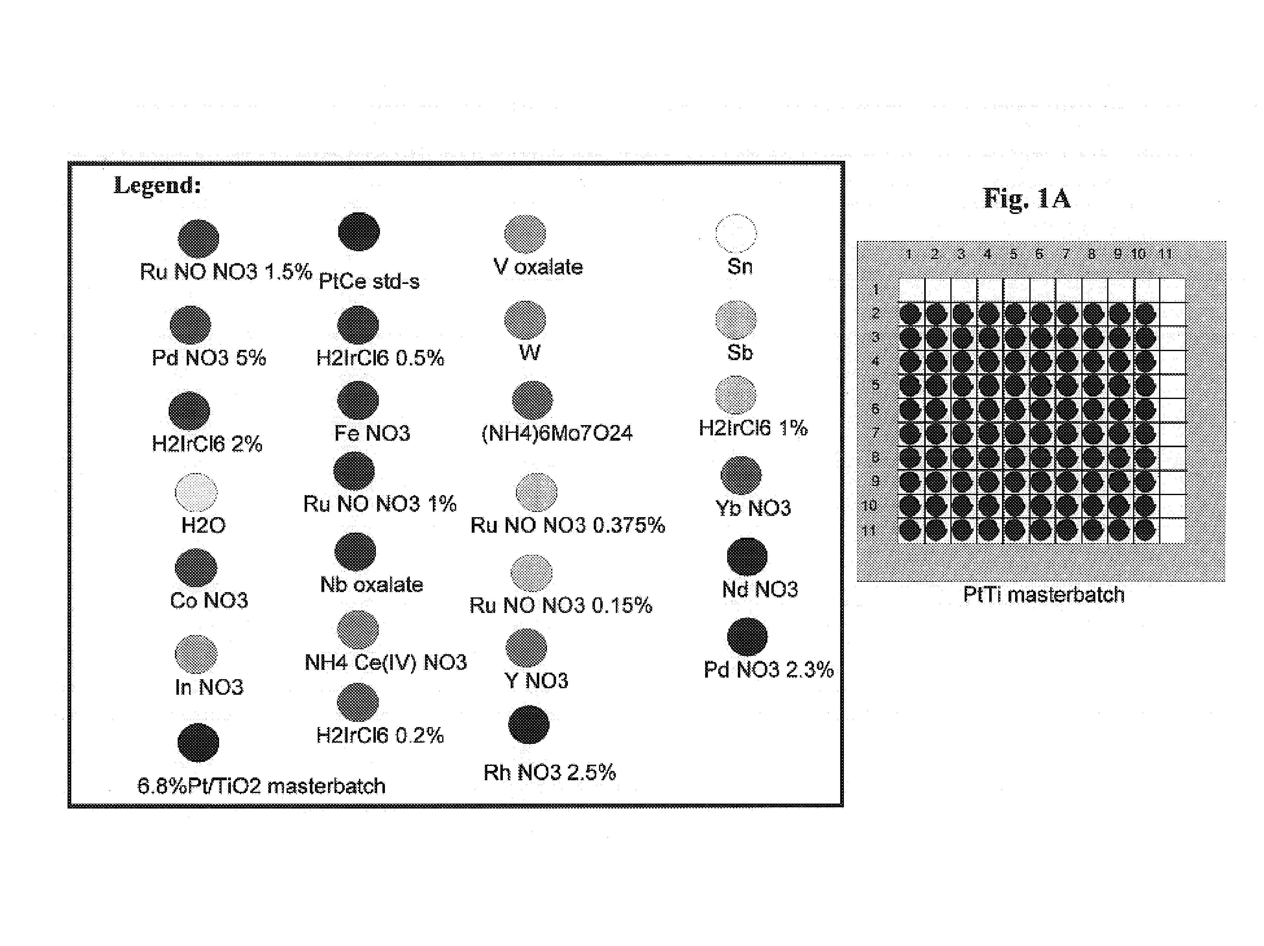
[0190]A 6.8% Pt / titania masterbatch was prepared by incipient wetness impregnation of 1000 mg titania powder (Degussa Aerolyst 7708, less than 100 mesh sieve fraction) with 1,300 μl of Pt(NH3)2(NO2)2 stock solution (5% Pt, STREM) and dried overnight at ambient, then at 80° C., then at 110° C.

[0191]500 mg of the 6.8% Pt / TiO2 masterbatch was slurried into 4 ml of EG / H2O / MEO 40 / 30 / 30 mixture and then slurry-dispensed onto a 3″ quartz wafer in two layers of 3 μl slurry each for a total dispense volume of 6 μl.

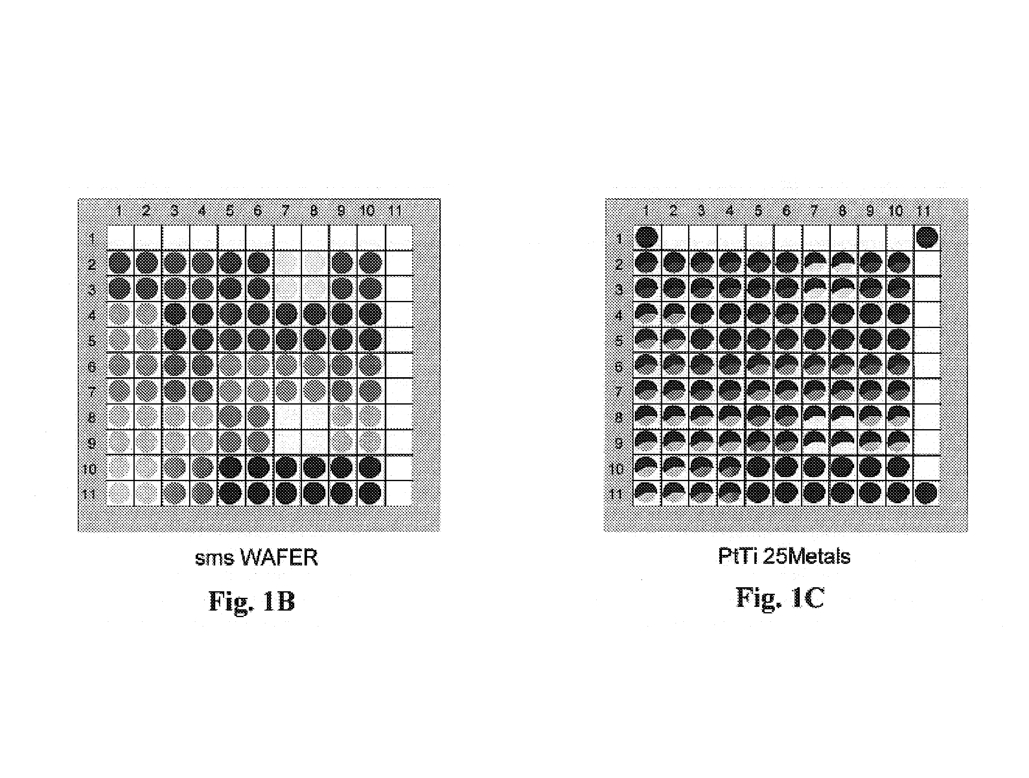
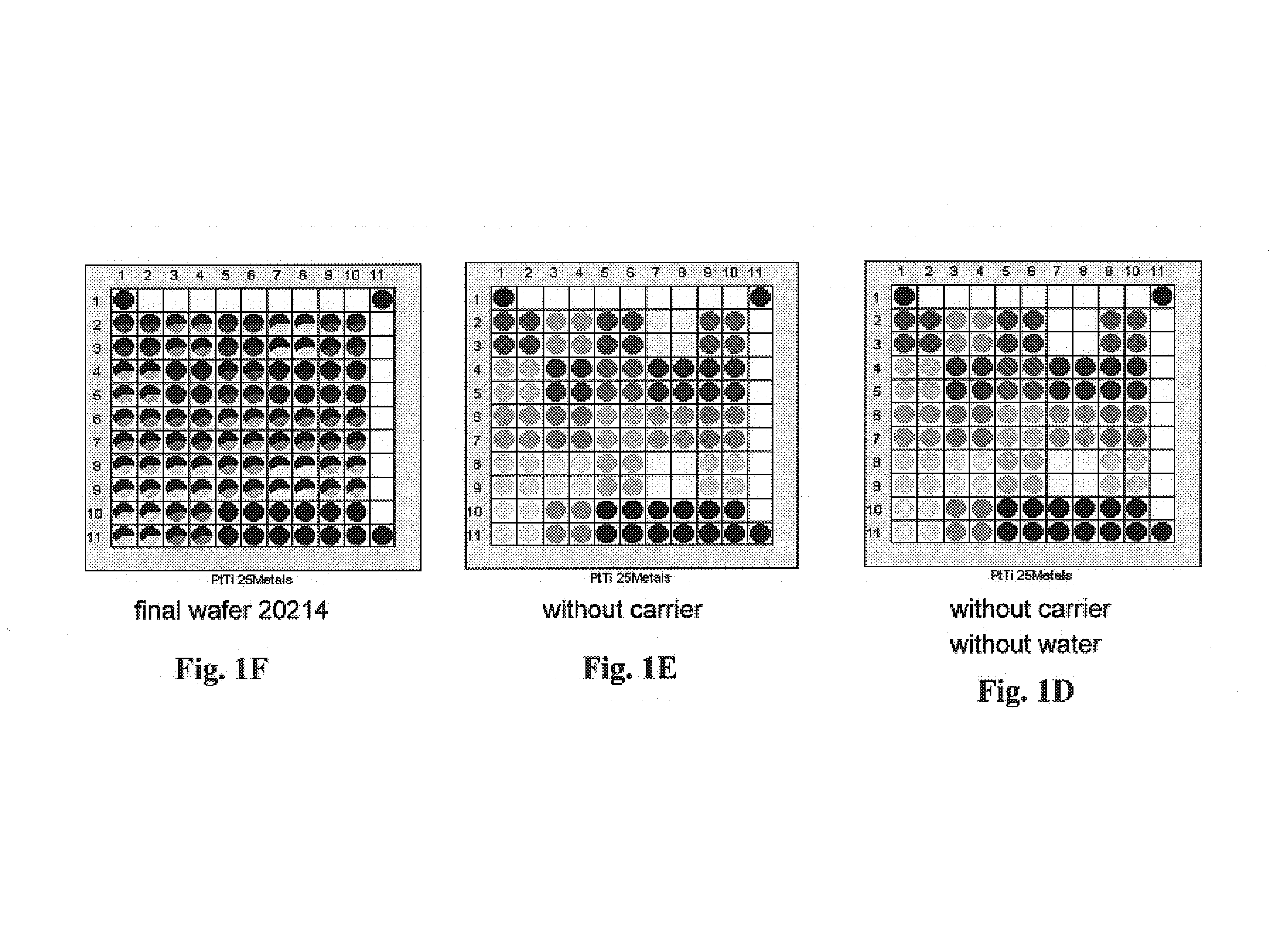
[0192]The Pt / TiO2 precoated wafer was then impregnated with 25 different metal solutions in squares of 2 by 2 wells by direct dispensing from metal stock solution vials onto the wafer at 2 μl dispense volume / well. The wafer was dried, calcined in air at 450° C. for 2 hours and then reduced in 5% H2 / Ar at 450° C. for 2 hours. See FIGS. 1A–1F.

[0193]The reduced library was then screened in scanning mass spectrometer (“SMS”) for WGS activity with a H2 / CO / CO2 / H2O mixed feed at 250° C., ...

example 2

[0194]A 3″ quartz wafer was precoated with TiO2, CeO2 and ZrO2 carriers by slurry dispensing (Degussa Aerolyst 7711 / Degussa P25 70:30 titania mix), (Aldrich ceria 21,157-5) and (Norton XZ16052 / MEI FZO923 70:30 zirconia mix) onto the wafer.

[0195]The carrier-precoated wafer was dried and then impregnated with Ru, Ce, Fe gradients. The Ru, Ce, Fe gradients were premixed in a microtiter plate by dilution of Ru nitrosyl nitrate stock solution (1.5% Ru), Ce nitrate stock solution (1M Ce) and Fe nitrate stock solution (1M Fe) with water and transferred from the microtiter plate to the wafer by Cavro dispensing (3 μl dispense volume per well). The wafer was dried and then impregnated with Ti gradients. The Ti gradients were premixed in a microtiter plate by dilution of ammonium titanyl oxalate stock solution (1M Ti) with water and then transferred from the microtiter plate to the wafer by Cavro dispensing (3 μl dispense volume per well). The wafer was dried and then impregnated with Pt grad...

example 3

[0197]A 4″ quartz wafer was precoated with zirconia carrier by repeated slurry dispensing zirconia (ZrO2 Norton XZ16052 / MEI FZO923 70:30 mixture, 2×4 μl for a total of 8 μl zirconia slurry, 1 g ZrO2 mix slurried in 4 ml EG / H2O 1:1) onto the wafer.

[0198]The zirconia carrier-precoated wafer was dried and then impregnated with Pt by Cavro dispensing from a Pt(NH3)2(NO2)2 stock solution vial (2.5% Pt) directly onto the wafer by 3 μl dispense volume / well. Six internal standards were spotted into 6 first row / last column wells (4 μl zirconia slurry+3 μl 2.5% Pt solution). The wafer was dried for 10 minutes at 70° C.

[0199]The wafer was then impregnated with Co—Ru and Ru—Pt gradients by Cavro dispensing from Co nitrate (0.5M Co), Ru nitrosyl nitrate (1% Ru) and Pt(NH3)2(NO2)2 (5% Pt) stock solution vials to a microtiter plate followed by transferring replicas of the 8-point and 7-point gradients onto the wafer at 3 μl dispense volume / well. The wafer was dried and then impregnated with FeCo b...


PUM

PropertyMeasurementUnit
temperatureaaaaaaaaaa

Abstract

A method and catalysts for producing a hydrogen-rich syngas are disclosed. According to the method a CO-containing gas contacts a water gas shift (WGS) catalyst, optionally in the presence of water, preferably at a temperature of less than about 450° C. to produce a hydrogen-rich gas, such as a hydrogen-rich syngas. Also disclosed is a water gas shift catalyst formulated from:a) Pt, its oxides or mixtures thereof;b) Ru, its oxides or mixtures thereof; andc) at least one of Li, Na, K, Rb, Cs, Mg, Ca, Sr, Ba, Sc, Y, Ti, Zr, V, Mo, Mn, Fe, Co, Rh, Ir, Ge, Sn, Sb, La, Ce, Pr, Sm, and Eu. Another disclosed catalyst formulation comprises Pt, its oxides or mixtures thereof; Ru, its oxides or mixtures thereof; Co, its oxides or mixtures thereof; and at least one of Li, Na, K, Rb, Cs, Mg, Ca, Sr, Ba, Sc, Y, Ti, Zr, V, Mo, Mn, Fe, Rh, Ir, Ge, Sn, Sb, La, Ce, Pr, Sm, and Eu, their oxides and mixtures thereof. The WGS catalyst may be supported on a carrier, such as any one member or a combination of alumina, zirconia, titania, ceria, magnesia, lanthania, niobia, zeolite, perovskite, silica clay, yttria and iron oxide. Fuel processors containing such water gas shift catalysts are also disclosed.

Description

CROSS-REFERENCE TO RELATED APPLICATIONS[0001]The present application claims benefit from earlier filed U.S. Provisional Application No. 60 / 434,708, filed Dec. 20, 2002, which is incorporated herein in its entirety by reference for all purposes. The present application also incorporates by reference the PCT International Patent Application No. US2003 / 040944 entitled “Platinum-Ruthenium Containing Catalyst Formulations for Hydrogen Generation” naming as inventors Hagemeyer et al. filed on the same date as the present application.BACKGROUND OF THE INVENTION[0002]1. Field of the Invention[0003]This invention relates to methods and catalysts to generate a hydrogen-rich gas from gas mixtures containing carbon monoxide and water, such as water-containing syngas mixtures. More particularly, the invention includes methods using both precious metal- and non-precious metal-containing catalysts. The catalysts may be supported on a variety of catalyst support materials. Catalysts of the inventio...

Claims


Application Information

Patent Timeline
Patent Type & Authority Patents(United States)
IPC IPC(8): C01B3/12C01B3/16B01J23/40B01J23/46B01J23/56B01J23/58B01J23/62B01J23/63B01J23/648B01J23/652B01J23/656B01J23/89B01J37/02C40B30/08C40B40/18
CPCB01J23/40B01J23/56B01J23/58B01J23/622B01J23/63B01J23/6482B01J23/6525B01J23/6562B01J23/89B01J23/8933B01J23/894B01J23/8993C01B3/16B01J23/462Y02E60/523B01J23/8946B01J37/024B01J2219/00585B01J2219/00596B01J2219/00605B01J2219/00612B01J2219/00637B01J2219/00641B01J2219/00659B01J2219/00662B01J2219/00691B01J2219/00702B01J2219/00707B01J2219/00745B01J2219/00747C01B2203/00C01B2203/0283C01B2203/1011C01B2203/1023C01B2203/1041C01B2203/1052C01B2203/1064C01B2203/107C01B2203/1082C01B2203/1094C01B2203/1614C40B30/08C40B40/18H01M8/0618H01M8/0668Y02E60/50Y02P20/52
Inventor HAGEMEYER, ALFREDCARHART, RAYMOND E.YACCATO, KARINSTRASSER, PETERGRASSELLI, ROBERT K.BROOKS, CHRISTOPHER JAMESPHILLIPS, CORY BERNARD
Owner FREESLATE
Why Eureka
Try Eureka