Dielectric resin foam and lens for radio waves using the same

a technology of dielectric resin foam and radio waves, applied in the direction of plastic/resin/waxes insulators, organic insulators, printed circuit details, etc., can solve the problems of inpracticality and substantially reduced mechanical strength of the resulting foam, and achieve the effects of reducing the number of insulating layers

Inactive Publication Date: 2007-02-20
OTSUKA CHEM CO LTD +1
View PDF16 Cites 32 Cited by
  • Summary
  • Abstract
  • Description
  • Claims
  • Application Information

AI Technical Summary

Benefits of technology

[0019]For example, a Luneberg lens which is equipped in a Luneberg lens antenna for tracking a low-earth-orbit satellite may have a dielectric constant of not less than 1.5 at 12 GHz and 25° C. and a specific gravity of not more than 0.5, and preferably a dielectric constant of not less than 2.0 and a specific gravity of not more than 0.5 under the above condition. The thus formed lens can cope with a high frequency band of not less than 10 GHz, specifically in the range of 12 to 20 GHz. Since the lens has such superior dielectric properties and low specific gravity, it can be miniaturized and weight-saved, for example, it may have a diameter of about 10 to 30 cm and a weight of about several kilograms.

Problems solved by technology

However, this transmission and receiving system can only handle a limited amount of information, which has caused a demand for a communication system capable of handling a larger amount of information.
Moreover, a large amount of powdery dielectric substance incorporated causes the mechanical strength of a resulting foam to be substantially decreased, which makes the foam impractical.

Method used


Image

  • Dielectric resin foam and lens for radio waves using the same
  • Dielectric resin foam and lens for radio waves using the same
  • Dielectric resin foam and lens for radio waves using the same

Examples


example 1

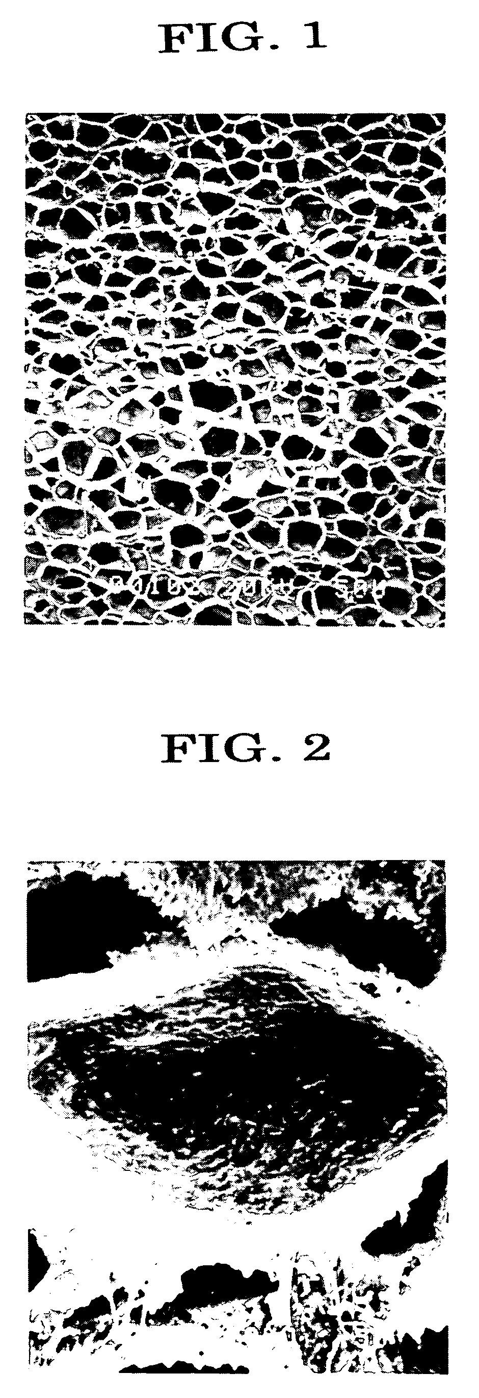
[0054]To polyethylene (LDPE, density 0.922, MFR 1.1, 100 parts by weight) were added azodicarbon amide (expansion agent, 5 parts by weight), plate-like calcium titanate (100 parts by weight) and dicumyl peroxide (crosslinking agent, 0.7 parts by weight), and the mixture was melt-kneaded with a mixing roll at 130° C., followed by pressing to have an expandable uncrosslinked sheet having a thickness of 3 mm.

[0055]The obtained expandable uncrosslinked sheet was put into a gear oven which had been heated to 160° C., and heated until the expansion ratio reached about 5 times, allowing the resin to be crosslinked and expanded. Thus, a foam having an expansion ratio of about 5 times was obtained.
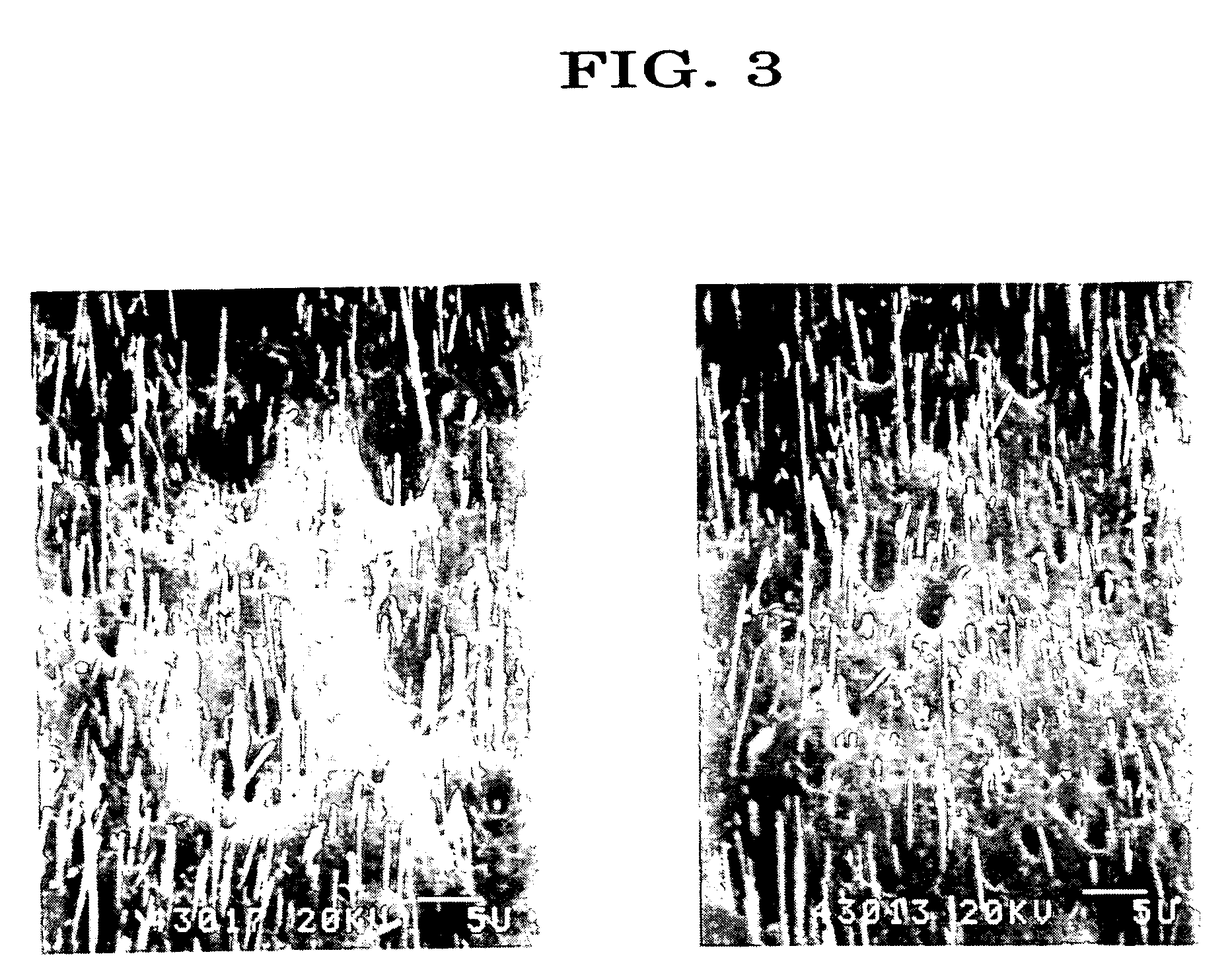
example 2

[0056]A foam having an expansion ratio of about 5 times was prepared according to a similar method to that of Example 1 except that fibrous calcium titanate was used instead of the plate-like calcium titanate.

example 3

[0066]A foam having an expansion ratio of about 5 times was prepared according to a similar method to that of Example 1 except that plate-like barium titanate (a mean long diameter of 10 μm, a mean short diameter of 6 μm, a mean thickness of 1.2 μm and an aspect ratio (mean long diameter / mean thickness) of 8.3) (200 parts by weight) was used instead of the plate-like calcium titanate.

[0067]The specific gravity of the obtained foam was 0.417. The dielectric constant and dielectric loss tangent thereof were 2.62 and 0.0130 respectively.


PUM

PropertyMeasurementUnit
specific gravityaaaaaaaaaa
dielectric constantaaaaaaaaaa

Abstract

It is an object of the present invention to provide a dielectric resin foam which has high and uniform dielectric properties and is preferable for use as various dielectric materials. A dielectric resin foam obtained by expanding a resin composition comprising a synthetic resin and a fibrous and/or plate-like dielectric inorganic filler is provided.

Description

TECHNICAL FIELD[0001]The present invention relates to a dielectric resin foam and a lens for radio waves using the same. More specifically, the present invention relates to a dielectric resin foam that has superior dielectric properties and is of a light weight, as well as being capable of being formed in a reduced size, enabling itself to be preferably used as a dielectric material for electronic devices in information and telecommunication fields such as an antenna, a condenser, a laminated circuit substrate, a connector, a memory and the like, and a lens for radio waves using the dielectric resin.BACKGROUND ART[0002]The recent drastic increase in the amount of signal information transmitted by a radio wave, which resulted from the remarkable improvement of information and telecommunication technologies, requires better accuracy and swiftness of the signal information and further increase in the amount of information, as well as has caused a rapid movement to the use of high-frequ...

Claims


Application Information

Patent Timeline
Patent Type & Authority Patents(United States)
IPC IPC(8): C08J9/00H01Q15/08C08J9/06C08J9/04C08J9/232C08K7/00C08K13/04C08L101/00C08L101/12H01B3/00H01B3/30H01B3/44H01Q15/02H01Q19/06H05K1/03
CPCC08J9/0066C08J9/0085H01B3/30H01Q15/02H01Q15/08H01Q19/062H01B3/441H05K1/0373C08J9/04H01B3/48H01Q3/24
Inventor AKI, MINORUMONDE, HIROYUKITABUCHI, AKIRATACHI, YOSHIFUMIKAWAKAMI, SYOUGOKURODA, MASATOSHIKISHIMOTO, TETSUOKIMURA, KOUICHI
Owner OTSUKA CHEM CO LTD
Why Eureka
Try Eureka