Exposure apparatus with laser device

a laser device and laser device technology, applied in the field of exposure apparatus, can solve the problems of increasing the difficulty of chromatic aberration compensation, increasing the complexity of configuration, increasing the cost, etc., and achieves the effect of facilitating alignment, increasing the maintainability of the apparatus, and miniaturizing the exposure apparatus

Inactive Publication Date: 2007-05-01
NIKON CORP
View PDF20 Cites 38 Cited by
  • Summary
  • Abstract
  • Description
  • Claims
  • Application Information

AI Technical Summary

Benefits of technology

[0027]The exposure apparatus in each of the above-described aspects of the present invention allows use of a light source which is small and which has a narrow oscillatory spectrum such as, for example, a distributed feed back (DFB) semiconductor laser controlled in oscillation wavelength or a fiber laser as the laser light generation section in the laser device. High-output single wavelength ultraviolet light which has a narrow spectral width can be obtained in the following manner. Single wavelength laser light output from the laser light generation section is amplified using the plural stages of optical fiber amplifiers; and thereafter, the laser light is converted into ultraviolet light through the nonlinear optical crystal. As such, the present invention enables the provision of the exposure apparatus including the laser device which is small and which has high maintainability.
[0045]According to an exposing method of the present invention, the ultraviolet light from the laser device is used as alignment light for an exposure apparatus of, for example, a TTR (through the reticle) method type, of the exposure apparatus. The alignment light can be formed to substantially be continuous light, thereby facilitating the alignment.

Problems solved by technology

Second, when the exposure light is ultraviolet light having a wavelength of 300 nm or shorter, an optical material which can be used for a reflector member (lens) of a projection optical system is limited, and hence the difficulty increases for compensation of the chromatic aberration.
This arises various problems.
For example, the transmittance of an optical component tends to vary because of so-called compaction and the like, complicated maintenance is required and hence costs are increased.
In this connection, these methods arises other problems.
For example, the aforementioned adjustment requires a sensitive arrangement; and in proportion to the increase in the constituent laser elements, the complexity of the configuration needs to be increased to cause the overall devices to oscillate with the same wavelength.
However, the method has problems in that it requires an optical system for separating the seed light into the individual laser elements and an oscillatory-wavelength tuning control section, thereby increase complexity of the configuration.
In addition, the array laser as described above enables the overall device to be significantly smaller than that with the conventional excimer laser, it still causes difficulty in packaging so as to reduce the diameter of overall arrayed output beams to several centimeters or smaller.
The array laser thus configured has additional problems.
For example, each of the arrays requires the wavelength modulator section, thereby increasing the cost.
In addition, suppose misalignment has occurred in a part of the laser elements constituting the array, or damage has occurred with the constituent optical elements.
However, when light having a high intensity is propagated by simply using the optical fibers, problems can occur in that the wavelength width of the propagated light expands because of the influence of various factors attributed to nonlinear effects of the optical fibers.

Method used


Image

  • Exposure apparatus with laser device
  • Exposure apparatus with laser device
  • Exposure apparatus with laser device

Examples


Embodiment Construction

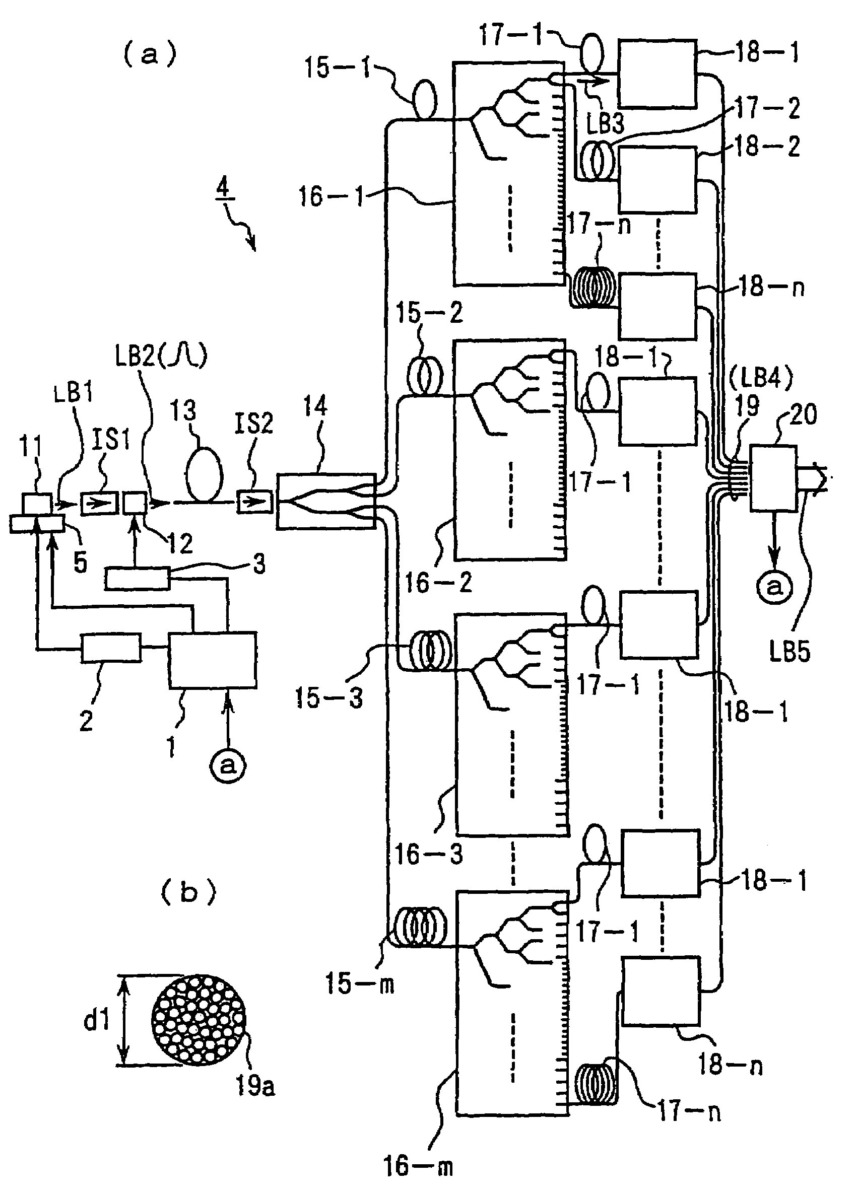
[0060]Hereinbelow, an example of a preferred embodiment according to the present invention will be described with reference to the accompanying drawings. The present example represents a configuration in which the present invention is applied to an ultraviolet light generator that can be used as a projection exposure apparatus such as a stepper method or a step-and-scan method, or as a light source for alignment and various tests.

[0061]FIG. 1A shows an ultraviolet light generator according to the present example. Referring to FIG. 1A, a single wavelength oscillatory laser 11, which is provided as a laser light generation section, generates a laser beam LB1 that is formed of a continuous wave (CW) having a narrow spectral width and that has a wavelength of 1.544 μm. The laser beam LB1 is incident on an optical modulating device 12, which is provided as an optical modulator, via an isolator IS1 provided for blocking reverse light. The laser beam LB1 is converted therein into a laser b...


PUM

PropertyMeasurementUnit
wavelengthaaaaaaaaaa

Abstract

A laser apparatus that includes a laser light generation section, an optical amplification section, a wavelength conversion section and a suppressing section is provided. The laser light generation section includes a single wavelength oscillatory laser and generates pulsed light having a single wavelength within a wavelength range ranging from about 1.51 to 1.59 μm. The optical amplification section includes an optical fiber amplifier and is optically connected to the laser light generation section to amplify the pulsed light. The wavelength conversion section includes a nonlinear optical crystal and is optically connected to the optical amplification section to perform wavelength conversion of the amplified pulsed light into ultraviolet light. The suppressing section suppresses expansion of a wavelength width of light originated in a nonlinear effect of an optical element between the single wavelength oscillatory laser and the wavelength conversion section.

Description

[0001]This is a Division of application Ser. No. 10 / 070,682 flied Sep. 4, 2002 now U.S. Pat. No. 6,947,123 which in turn is a National Stage of Application No. PCT / JP00 / 06130 filed Sep. 8, 2000. The entire disclosure of the prior applications is hereby incorporated by reference herein in their entireties.TECHNICAL FIELD[0002]The present invention relates to an exposure apparatus including a laser device which generates ultraviolet light. More specifically, the present invention is preferably used as an exposure apparatus used in a photolithography process for manufacturing microdevices, such as semiconductor devices, image pickup devices (such as CCDs), liquid crystal display devices, plasma display devices, and thin-film magnetic heads.BACKGROUND ART[0003]For example, an exposure apparatus used in a photolithography process for manufacturing a semiconductor integrated circuit optically reduces and projectively exposes a circuit pattern accurately rendered on a reticle (photomask) u...

Claims


Application Information

Patent Timeline
Patent Type & Authority Patents(United States)
IPC IPC(8): G03B27/54G02F1/35G03B27/72G03F7/20G03F9/00H01S3/00H01S3/067H01S3/094H01S3/109H01S3/131H01S3/16
CPCG03F7/70041G03F7/70575G03F9/7065H01S3/06758H01S3/06754H01S3/2375H01S3/2383H01S5/06804H01S5/0687H01S3/0092G03F7/70025G02F2001/354H01S2301/02H01S3/005H01S3/0064H01S3/0078H01S3/0085H01S3/094011H01S3/094015H01S3/1608H01S3/09415G02F1/354
Inventor OHTSUKI, TOMOKO
Owner NIKON CORP
Why Eureka
Try Eureka