
Microwell biochip

a microwell and biochip technology, applied in the field of microwell biochips, can solve the problems of optically obtaining accurate quantitative assays, fluid handling difficulties, and additional costs of producing such high density microtiter plates, and achieve the effects of high throughput assay capabilities, simple and versatile forma

Inactive Publication Date: 2007-05-15
BIOCEPT INC
View PDF29 Cites 109 Cited by
  • Summary
  • Abstract
  • Description
  • Claims
  • Application Information

AI Technical Summary

Benefits of technology

"The present invention provides a multiwell / microwell assay plates that use a hydrogel polymer for immobilizing biological materials. The plates have multiple wells with support material that functions as probes, and the biological materials are immobilized on the surface of each well at a predetermined location. The plates can be used for high throughput assay capabilities in a simple and versatile format. The invention also provides a method for making the plates and a method for using them for biological assays. The invention also provides a device for holding a liquid solution and allowing the reaction thereof with immobilized biological material as a part of an assay, which device comprises a plate in which there are formed a group of wells wherein the walls of the wells are substantially liquid impervious, a microporous material closing the bottom of each well, and at least one spot of a polymer attached to the upper surface of the microporous bottom of each well, which spot comprises a crosslinked hydrogel polymer having biological material so immobilized on or within the polymer as to be contactable by a liquid supplied to the well. The invention also provides a method of making the device and a method of using it for biological assays."

Problems solved by technology

However, such higher well densities in a conventional microtiter plate assay present three main challenges: 1) the additional cost associated with producing such high density microtiter plates, 2) the difficulties with fluid-handling due to small well volumes, and 3) difficulties with optically obtaining accurate quantitative assay results.

Method used


Image

  • Microwell biochip
  • Microwell biochip

Examples


example 1

Preparation of Microwell Biochips

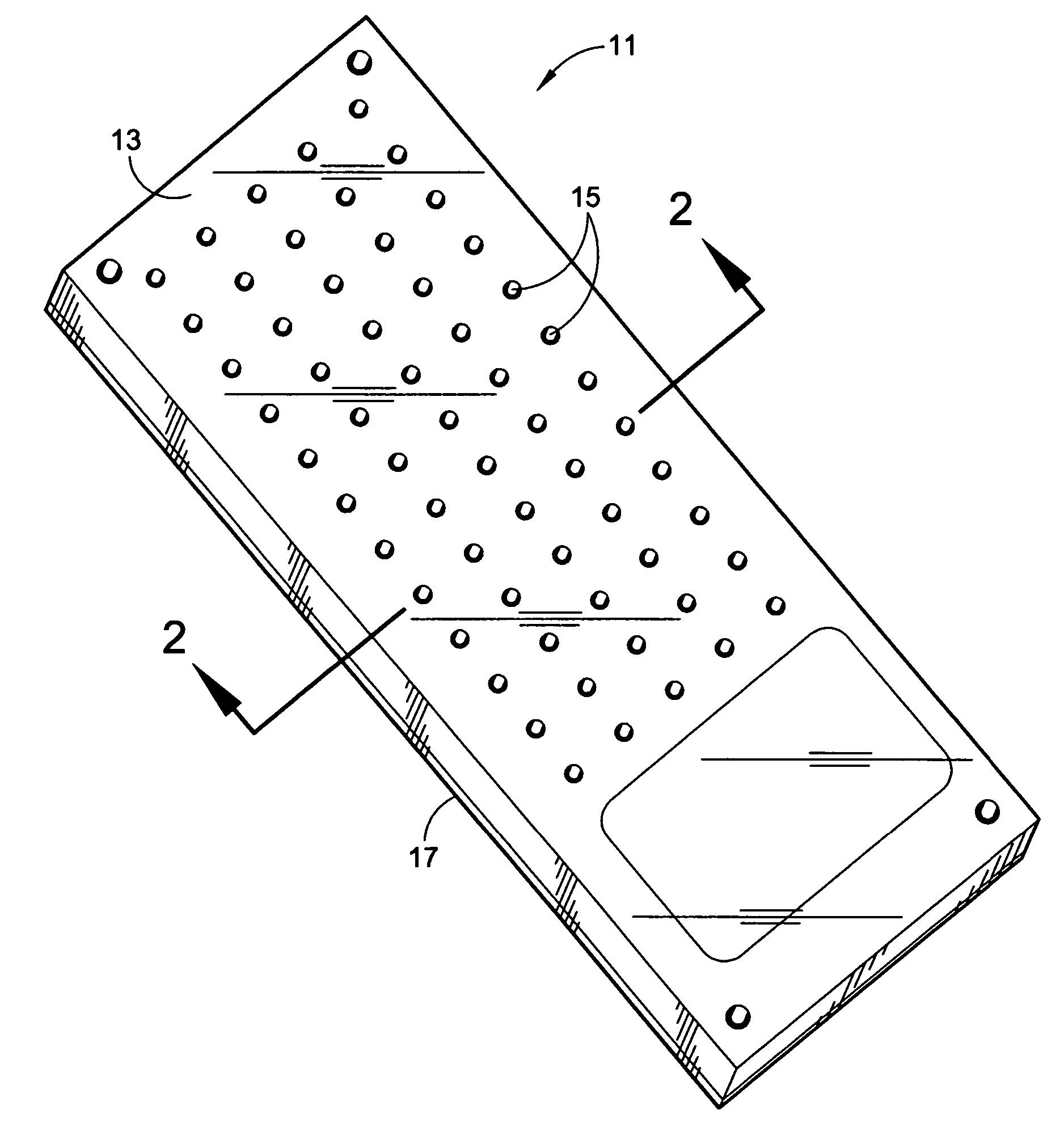
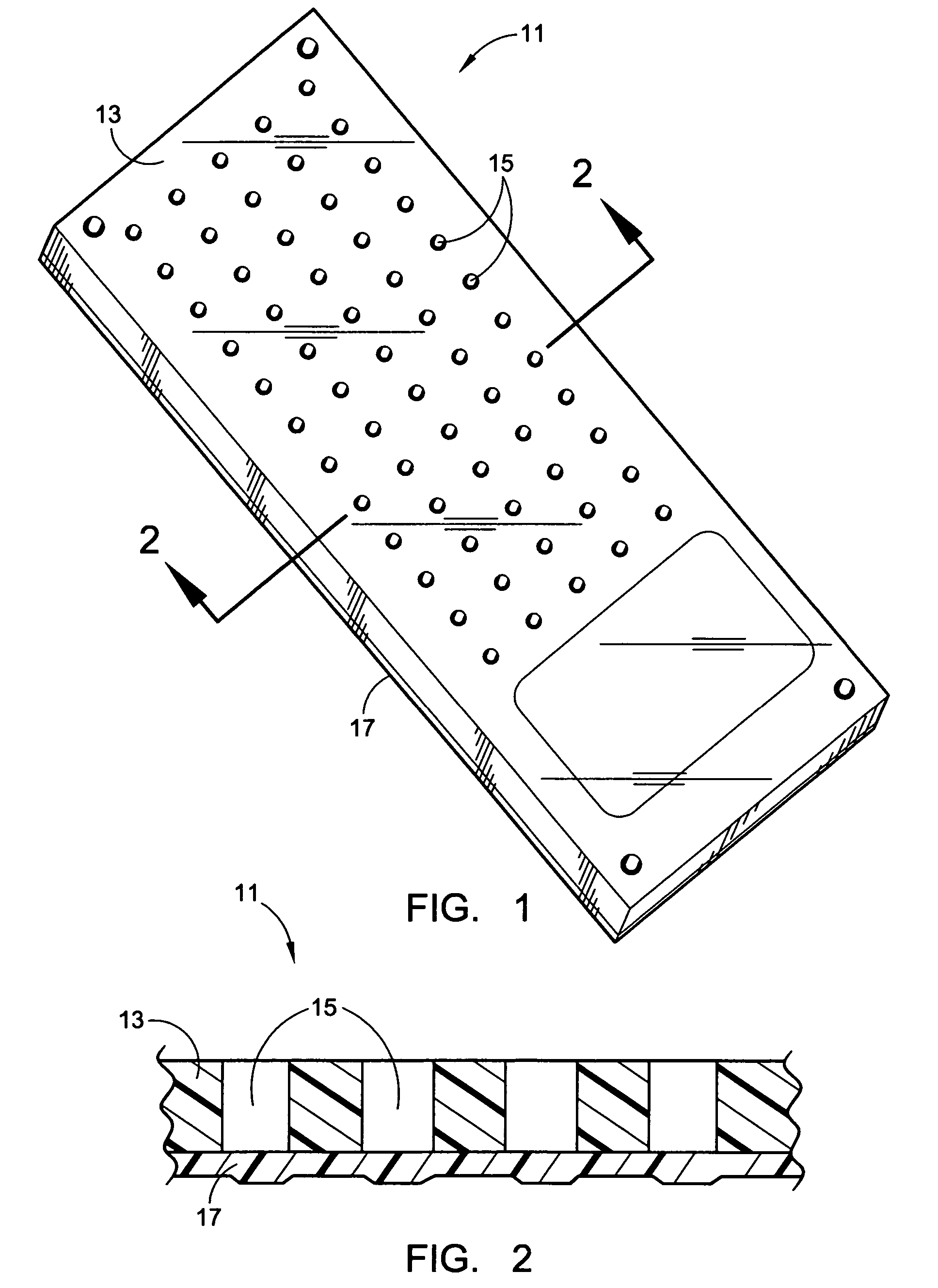
[0026]A sample microwell biochip 11 was advantageously designed to be similar in size and shape to a common (2.54×7.62 cm) microscope slide. Sixty 1.3 mm diameter holes 15 were drilled through a black polycarbonate plate 13 about 1 mm thick using a standard microtiter plate configuration (e.g. 4.5 mm pitch). In order to further decrease background during optical scanning, the plate was spray painted (prior to lamination) to give it a matte black finish.

[0027]A 0.45 μm pore size polypropylene membrane 17 (Osmonics, Inc., Minnetonka, Minn.) was laminated to the undersurface of the plate by applying spray-on adhesive to the plate and pressing the membrane in place to create this sample multiwell chip; however, it should be understood that ultrasonic welding is preferred. The membrane 17 exhibited a smooth hydrophobic surface, thus ensuring good spot morphology. This small pore membrane retains aqueous samples in the wells during binding / hybridization ev...

example 2

Printing and Hybridizing with a Microwell Protein Biochip

Protein Formulations for Printing

[0028]A mixture of Anti-transferrin antibody in Hypol (Hampshire Chemical Corporation, Lexington, Mass.) and nonspecific IgG in Hypol (as blank control) were printed and then tested with Cy3-labeled transferrin. HYPOL is an isocyanate-capped PEG prepolymer that is believed to be well-suited for this application. Both samples were formed as 3.3 weight % solutions of HYPOL (1:3:3=Prepolymer:Acetonitrile:NMP), which contained 5% Trehalose (protein preservative sugar), 100 mg / ml IgG (protein filler), 0.5% Glycerol (humectant), and either 0.8 mg / ml anti-transferrin (positive) or 1 mg / ml Bovine IgG (negative).

Printing

[0029]Printing was performed using a Cartesian array printing system (Cartesian Technologies, Inc., Irvine, Calif.) and 300 micron inside diameter glass capillary pins (Humagen Fertility Diagnostics, Inc., Charlottesville, Va.). Hydrogel spots having an approximately 310 micron diameter ...

example 3

Imaging

[0031]In order to measure the fluorescence of microwell biochip, a charge-coupled device-based scanner was constructed using a CCD camera. Even though current dimensions of the chip allow for scans in a conventional microarray laser scanner, a CCD camera offers greater flexibility in terms of depth of focus, thickness and width of the chip. In the embodiment employed, the chip was placed on a movable stage with the CCD camera positioned directly above. Excitation light, provided by a halogen bulb, passes through a dichroic mirror, and the emission light is collected by the CCD. The dichroic mirror is set to collect data in the Cy3 fluorescent dye range. A variety of other dichroics can be substituted into the camera, thus allowing a choice from a wide range of dyes, e.g. fluorescein, Cy5. The stage can be moved either manually or through programming of different scan coordinates into the camera software. Focus, camera sensitivity, and camera exposure times are varied as neces...


PUM

PropertyMeasurementUnit
pore sizeaaaaaaaaaa
thicknessaaaaaaaaaa
thickaaaaaaaaaa

Abstract

Microwell biochips (11) are formed from a thin flat plate (13) of polymeric material having a plurality of regularly spaced holes (15) that extend completely therethrough and create microwells. The lower end of each hole is closed by a microporous, hydrophobic, polymeric membrane (17) laminated to the undersurface of the plate which retains an aqueous test solution in the wells until a vacuum is applied to the undersurface thereof to effect draining of the solution and of any wash solution that might be subsequently added. A spot of polymerizing isocyanate-functional hydrogel is applied generally centrally to the porous membrane surface at the bottom of each well in a manner so as to cover only a minor portion of the surface and out of contact with the well sidewalls, thus leaving substantial surface area through which drainage can be readily effected. Biological capture agents are associated with the polymerizing hydrogel so as to become immobilized as a part thereof.

Description

[0001]This application is a continuation of PCT / US02 / 32751, filed Oct. 15, 2002 and claims priority from U.S. Provisional Application Ser. No. 60 / 329,632, filed Oct. 15, 2001, the disclosures of both of which are expressly incorporated herein by reference. This invention relates to devices for carrying out bioassays, to methods for making such devices, and to methods for assaying using such devices.BACKGROUND OF INVENTION [0002]High throughput screening is a term used to describe a method where many discrete assays are performed in parallel. Currently, the most widely established techniques utilize 96-well microtiter plates. Such microtiter plates have been used for decades in research and clinical laboratory practice, as they provide an easy method for increasing assay throughput. Typically made of polystyrene, such microtiter or microwell plates provide 6 to 96 individual wells, in which a matrix of samples can be mixed with reagents, agitated, incubated and the like, either manua...

Claims


Application Information

Patent Timeline
Patent Type & Authority Patents(United States)
IPC IPC(8): C12Q1/68C07H21/04C07K5/00C12M1/36G01N15/06B01D61/18B01J19/00B01L3/00C40B40/06C40B40/10C40B60/14G01N21/03G01N33/543G01N33/566
CPCB01D61/18B01L3/50255G01N21/03G01N33/54366G01N33/54393B01J2219/00286B01J2219/00317B01J2219/00385B01J2219/00423B01J2219/00576B01J2219/00702B01J2219/00722B01J2219/00725B01J2219/00743B01L2200/0689B01L2200/12B01L2300/0819B01L2400/049C40B40/06C40B40/10C40B60/14G01N2021/0346
Inventor TSINBERG, PAVELROYCROFT, PATFALCOVITZ-GERASSI, YEHUDIT HANNAHHAHN, SOONKAP
Owner BIOCEPT INC
Learn More