Projection screens do not perform well in conditions of strong ambient light.
Many of the
metrics of quality for an image projected onto a screen are seriously degraded even when ordinary room lighting illuminates a
projection screen.
The incidence of direct
sunlight on a screen typically destroys in totality every metric of the image's quality.
Prior art has attempted to overcome the degradation of projection screen
metrics, but the complex problem of maintaining high quality under severe
environmental lighting conditions has until now eluded solution.
Although an art may preserve one or several of the metrics of
image quality, each prior art fails, in strong ambient light, to provide preservation of the complete array of metric levels characteristic of high quality imagery.
As will be understood from discussion below, unitary-
gain screens are not amenable to operation in strong ambient light.
For many reasons
diffraction-based screens are poor candidates for operation in strong ambient light.
Much of the problem can result from residual
diffusion areas, though inability to obtain desired reflection-element figure for controlled dispersion can be a factor also.
No reflective-morphology prior art has preserved high enough performance in all the metrics needed for maintenance of quality imagery under such conditions, however.
This is so even though the diffuse scatter has been reduced to a fraction of the dispersed (redirected) light; it just cannot be reduced enough with prior art to solve the problem of strong ambient light.
As with glass bead screens, the other catadioptric screens are not suitable in additional regards, such as
broadband spectral operation and maintenance of image
darkness as needed to preserve
high contrast ratios.
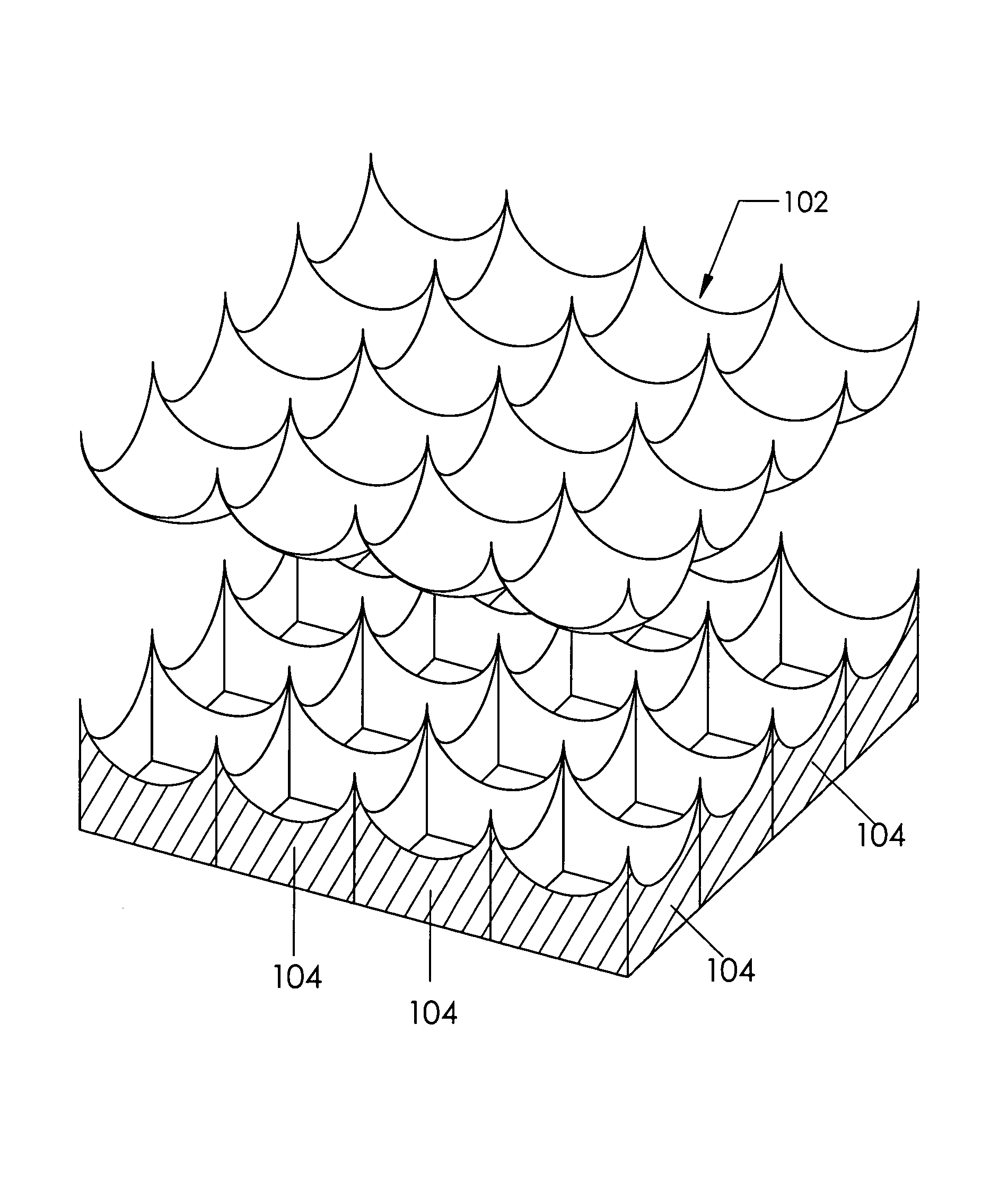
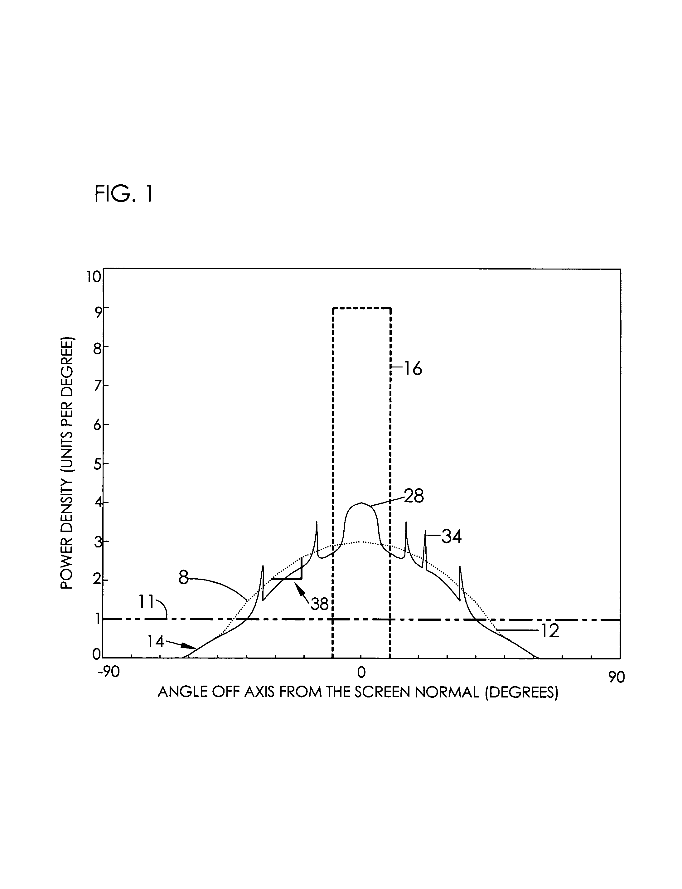
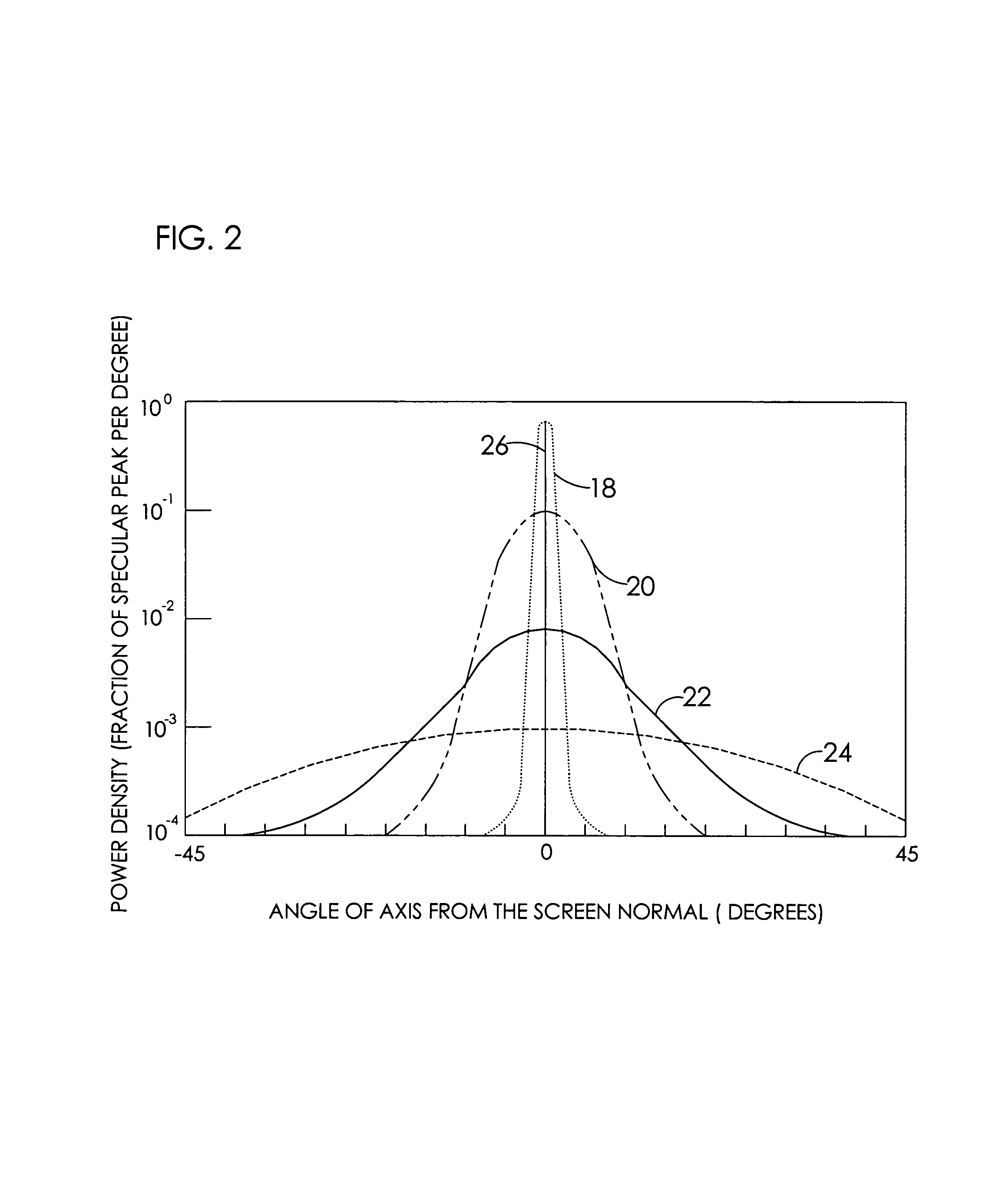
However, prior art attempts to make large mirrorlette arrays with the profiles of curve 16 have been unsuccessful because the basic concepts associated with proposed assemblies failed to account for the difficulties of making an array of even hundreds of thousands, let alone the needed millions, of very small,
optical quality elements.
However, for several reasons, including
micrometer-sized variations in chemical reactivity for chemical processes and
electric field variations for electronic processes, neither of these options is readily applicable to achieving curve 20 or better on a large scale in the laboratory, let alone is any of them commercially practical.
Similar phenomena negate the use of plating techniques to achieve an infilling of roughness that remains after
machining of the mirrorlettes.
Pleasing shininess is achievable with curve 24, but it does not support
high resolution.
Even a small residual of diffuseness resulting from less than optical quality sub-
wavelength finish will negate the ability to reject strong
environmental lighting.
Another hurdle associated with
machine-made and subsequently optically polished mirrorlettes is the extreme difficulty in fabrication of convex mirrorlettes.
Such narrowness in an array of tens or hundreds of thousands of mirrorlettes per
square meter is exceedingly difficult to maintain.
With concave mirrorlettes, a curved
cutting tool easily and consequently produces narrow edges, but these are ridges that are easily damaged in situations associated with common use of projection screens.
(Further, such ridges have electrostatic consequences.)
Another shortcoming of prior art is its inability to provide a high-quality screen with real-
time variable gain.
In essence, prior art adjustability fails to provide a projection high-gain screen with real-
time variable gain.
Techniques of this nature produce curved
specular surface cells with a desirable shape for high gain over the center of each mirrorlette
cell, but that also produce notably excessive gain (in essence a glare) rather than uniform dispersion of the
projector light.
The cusp-like grooving technique used in the
electroforming approach of U.S. Pat. No. 3,994,562 to Holzel (1976) somewhat alleviates glare, but at the severe expense of excessive scattering of off-axis
background light due to the finish limits of
electroforming.
Also, this prior art has practical limitations in seamless screen size.
(1977), wherein concave cells were individually constructed, with the attendant
disadvantage in production simplicity and the
exposure to damage of the
cell edges because of the concave architecture.
However such screens perform poorly in many of the other screen metrics when they are operated in strong ambient light.
However, as expected with stochastic events, probabilities exist that an occasional integration region will still be excessively brighter than its neighbors and appear as a speckle.
By the very nature of a
holographic screen, it is exceedingly vulnerable to ambient light, will not sustain color integrity, has significant brightness sidelobes, and is
highly sensitive to mechanical displacement.
Enhanced-gain screens of the catadioptric type using prior art have no significant capability for attaining sharp cutoff and wide viewing angles simultaneously.
However, their rate of cutoff, when scaled as a fraction of the total angular extent, is not selectable; nor does it approach 99% per degree on all viewing volume edges.
Prior art does not accommodate decoupling of the ability to control angular cutoff rates from the ability to control angular viewing volume.
In order to efficiently provide a viewer with a high-contrast projected image in bright ambient light, the availability of high-screen gain is not sufficient.
For impingement of direct
sunlight on a high-gain glass bead screen the ratio typically deteriorates to 1, which means the complete loss of a viewer's ability to see the projected image.
Clearly, the dark components in a projected image are the most vulnerable to strong environmental light.
The majority of prior art screens have been relegated to use in subdued lighting, or to accepting the multiple metric deficiencies using the limited capabilities of prior art attempts to design screens suitable to strong ambient light.
These latter prior arts unfortunately destroy the ability to employ polarization advantages that are discussed later, and they also decrease screen gain.
Deflection of impinging bright non-
projector light away from the viewing volume requires an
optical surface and a
cell figure that is not practically achievable for large arrays of small mirrorlettes using prior art.
However, prior art for background rejection including the use of mirrorlettes fails to achieve suitable metric levels for the complete set of other desirable screen attributes.
However, for very bright environments the ability of prior art to conserve gray scale
linearity is significantly limited for the same reasons presented in the contrast discussion.
Further, the needed projection lamp power would likely burn up the
image storage medium.
Values below 0.5 noticeably degrade viewed
image quality relative to the projected image.
If it falls off too rapidly, then the viewer may not be pleased with the image.
This means that the maximum brightness level is governed by the poorest unadjusted element, which provides for very inefficient use of projection energy.
In such circumstances, the result will be a non-uniform viewer image.
However, ambient light generally has characteristics that cause both desaturation and change in
hue of projected images at the same time.
And prior art is unable to drastically reduce color desaturation and
hue shift while still retaining the other needed attributes that are being delineated in this discussion of image metrics.
In fact, some techniques used to increase screen gain, as with glass bead and
lens array catadioptric screens, introduce additional problems, such as chromatic effects due to the beads having different refractive indices for different colors.
Regarding preservation of resolution using prior art: Another effect of ambient light is loss of
image resolution, which manifests itself to a viewer in many ways, including added difficulty in perceiving faint objects near bright objects and reducing the ability to separate fine detail.
Because of the scattering of light transversely within many unitary gain screen designs, such as plastic
diffusion films, there is considerable loss in ability to see small detail.
Thus, while prior art mirrorlette screens can offer reduction in transverse scatter compared to unitary-gain screens and catadioptric screens, the glare components of prior art mirrorlette screens will deteriorate
image resolution as well.
Further, mirrorlette screens based on drawing-out melted plastic shapes are vulnerable to surface striations and inhomogeneities that add to glare and speckle.
Because of the practical size considerations for such optical
polishing processes, the
resultant mirrorlette cell sizes are too large for close viewing as would be characteristic of conference rooms, in-door motion picture theaters,
home entertainment centers, and simulators.
This limitation leads to an inability to maintain the resolution of projected images, and in cases of the larger mirrorlette sizes, will lead to Moire patterns.
Modern sampling theory shows this suggestion to be without merit, however.
Prior art in mirrorlette techniques cannot provide a high metric value in this arena, for typical requirements of screen resolution and viewing distance, and still demonstrate good values in the other metrics.
Regarding minimization of
depolarization using prior art: Beyond the aforementioned shortcomings of catadioptric screens for
bright light environments, it is found that reflections from glass bead screens, and from most
lens array screens, do not maintain the polarity of incident light.
This is a serious drawback whenever the use of polarized differentiation is desired.
However, because a glass bead screen and other catadioptric screens do not adequately maintain the projected image polarizations upon reflection of the projected light, 3D is lost and the gain afforded by the screen for normal viewing is useless.
This was a major element in the lack of 3D development.
The
projector intensity had to be so great to overcome the loss in transmission through the viewing glasses that film was overheated and prematurely deteriorated.
Also, because even no-gain screens do not maintain fidelity of polarization, the
image separation was still poor.
The result was overlapping and cross-feeding between the eyes, which gave
headaches and
eyestrain to the viewers, as well as presented poor imagery.
However, prior art screens would not provide minimization of
depolarization at the same time that glare, speckle, uniformity, resolution, and
darkness metrics are met for strong environmental light applications.
None of the projection screen prior art that is based on catadioptric techniques can accommodate this range of projection spectra.
Accordingly, a screen such as a glass bead screen not only lacks gain at wavelengths outside of the visual spectrum, it is not even functional outside that spectrum.
This means the screen cannot be used in arcades where the designating light from the guns is too far into the
ultraviolet or the
infrared realms.
It also means that glass-bead screens cannot be used for
simulation of
thermal infrared screens, as in desirable for such activities as military training and night-vision equipment development.
Enhanced-gain mirrorlette screens defined in prior art can increase the range of spectral performance beyond the visual realm, but not with preservation of good metrics for resolution, glare, speckle, uniformity, and sharp angular cutoff.
Although there may be many variations in unitary screen approaches, few are outlandishly expensive or operationally impractical; and few are likely to fail because of an error in a basic concept.
Enhanced-gain reflection-only screens have not been as successful in the marketplace as the aforementioned architectures.
Production cost is a major factor.
For example, an Internet and literature survey to locate a screen having the architecture of U.S. Pat. No. 4,235,513 to Vlahos (1980) was unsuccessful.
Likewise, efforts to find screens based on the concepts of U.S. Pat. No. 4,235,513 to Vlahos (1980) were also unsuccessful.
In this latter case, the lack of large-scale commercialization may have had basic technical origins.
Further, the formation of the bubbles and the array is not likely to behave like a group of
soap bubbles.
Clearly, results of experiments with
soap bubbles cannot be automatically extended to other bubbles, including the effects of lateral stretching of a contiguous sheet of bubbles.
Further, patents based on erroneous assumptions may fail in the marketplace because they do not work as expected.
However, the ability to realize a technically and commercially viable mirrorlette array has not been available using prior art.
Rather, the problem of progress in screens has been that a viable method of manufacture for such arrays has been elusive, and even an optimal mirrorlette figure has been overlooked for lack of understanding.

