
Method for reducing wear of steel elements in sliding-rolling contact

a technology of sliding-rolling contact and steel elements, which is applied in the direction of rail lubrication, rail wetting/lubrication, manufacturing tools, etc., can solve the problems of uneven wear of mechanical components, high noise level of steel-rail and steel-wheel transportation systems, and large noise of mechanical components such as wheels, rails and other rail components, so as to reduce the amount of composition , the effect of high positive friction

Inactive Publication Date: 2007-07-17
KELSAN TECH
View PDF28 Cites 26 Cited by
  • Summary
  • Abstract
  • Description
  • Claims
  • Application Information

AI Technical Summary

Benefits of technology

"The present invention relates to a method for controlling wear of rails and rail car wheels in sliding or sliding-rolling contact. The method involves applying a high positive friction (HPF) composition to one or more of the contacting surfaces of the rails and rail car wheels. The HPF composition includes a rheological control agent, a lubricant, a friction modifier, and one or more of a retentivity agent, an antioxidant, a consistency modifier, and a freezing point depressant. The method can be used to control wear of both low and high rails, and can be carried out without the application of a trackside grease lubricant."

Problems solved by technology

For example; many steel-rail and steel-wheel transportation systems including freight, passenger and mass transit systems suffer from the emission of high noise levels and extensive wear of mechanical components such as wheels, rails and other rail components such as ties.
The origin of such noise emission, and the wear of mechanical components may be directly attributed to the frictional forces and behaviour that are generated between the wheel and the rail during operation of the system.
However, because the wheel and the rail are profiled, often misaligned and subject to motions other than strict rolling, the respective velocities at which the wheel and the rail move through the zone of contact are not always the same.
This is not possible on most fixed-axle railcars.
Sliding movement may also arise when traction is lost on inclines thereby causing the driving wheels to slip.
At creepage levels larger than about 1%, appreciable frictional forces are generated due to sliding, and these frictional forces result in noise and wear of components (H. Harrison, T. McCanney and J. Cotter (2000), Recent Developments in COF Measurements at the Rail / Wheel Interface, Proceedings The 5th International Conference on Contact Mechanics and Wear of Rail / Wheel Systems CM 2000 (SEIKEN Symposium No. 27), pp.
Unfortunately, it is often impossible to impart greater rigidity to a mechanical system, such as in the case of a wheel and rail systems used by most trains.
Alternatively, reducing the frictional forces between the wheel and the rail may greatly hamper adhesion and braking and is not always suitable for rail applications.
It is also known that, wear of train wheels and rails may be accentuated by persistent to and fro movement resulting from the presence of clearances necessary to enable a train to move over a track.
Corrugations increase noise levels beyond those for smooth rail-wheel interfaces and ultimately the problem can only be cured by grinding or machining the rail and wheel surfaces.
This is both time consuming and expensive.
However, the product does not display a positive friction characteristic.
Also, the product is a solid composition with poor retentivity.
However, the compositions do not have positive friction characteristics.
Furthermore, there is no indication that these compositions are optimized for durability or retentivity on the surfaces to which they are applied.
There are several drawbacks associated with the use of compositions of the prior art, including solid stick compositions.
First, outfitting railcars with friction modifier stick compositions and applying to large stretches of rail is wasteful if a noise problem exists at only a few specific locations on a track.
Second, some railroads have a maintenance cycle that may last as long as 120 days.
There is currently no stick technology that will allow solid lubricant or friction modifiers to last this period of time.
Third, freight practice in North America is for freight cars to become separated all over the continent, therefore friction modifier sticks are required on many if not all rail cars which would be expensive and impractical.
In such a system, solid stick technology may be less practical.
As many lubricant compositions of the prior art are either formulated into solid sticks or are viscous liquids (pastes), they may not be applied to sliding and rolling-sliding systems as an atomized spray.
Furthermore, atomized sprays dry rapidly which may lead to minimizing the potential for undesired locomotive wheel slip.
Such specific application is not possible with the solid delivery system that continually applies product to the wheels.
Furthermore the low transference rate of the solid stick application method will not yield any benefits until the track is fully conditioned.
This is an unlikely situation for a Class 1 rail line due to the extensive amount of track that must be covered and the presence of rail cars not possessing the solid stick lubricant.
However, this is not always true as the ability of the applied film to remain adhered to the rail and provide friction control is limited.
While exhibiting several desirous properties relating to frictional control, these composition exhibit low retentivity, and do not remain associated with the rail for long periods of time, requiring repeated application for optimized performance.
Also, as these compositions are water-based, the lower limit of the temperature range within which they can be used is limited.
These compositions are useful for specific applications, however, for optimized performance repeated re-application is required, and there is an associated increase in cost.
Furthermore, due to several of the characteristics of these liquid compositions, these compositions have been found to be unsuitable for atomized spray applications.
If applied to the top of the rail, these types of lubricants require sophisticated, complicated and expensive control systems to avoid problems of wheel slip or braking.
Although quantitative relationships are hard to come by, it is understood that high lateral forces are a significant factor in accelerated track structure degradation, rail wear, and rail rollover derailments.

Method used


Image

  • Method for reducing wear of steel elements in sliding-rolling contact
  • Method for reducing wear of steel elements in sliding-rolling contact
  • Method for reducing wear of steel elements in sliding-rolling contact

Examples


example 1

Characterization of Liquid Friction Control Compositions

Amsler Protocol

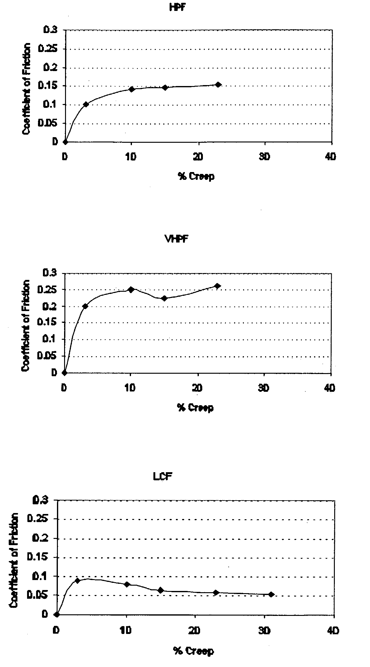
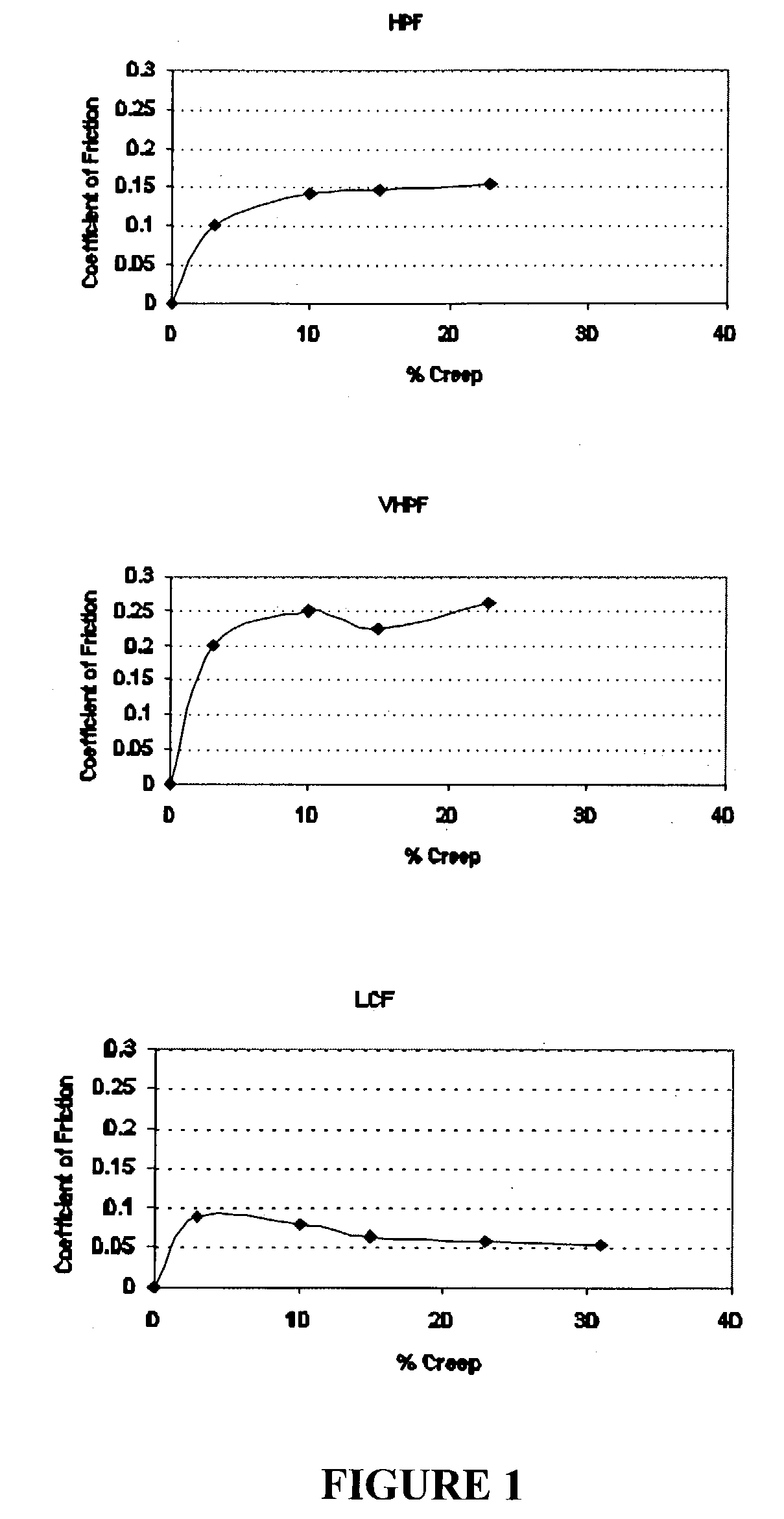
[0257]Retentivity was tested using the Amsler machine. This device simulates the contact between the wheel of a train and the rail, and measures the coefficient of friction between the two bodies over time. The Amsler machine uses two different discs to simulate the wheel and rail. The two discs are kept in contact by an adjustable spring at a constant force. A composition is applied to a clean disc in a controlled manner to produce a desired thickness of coating on the disc. For the analysis disclosed herein the compositions are applied using a fine paint brush to ensure complete coating of the disc surface. The amount of applied composition is determined by weighing the disc before and after application of the composition. Composition coatings range from 2 to 12 mg / disc. The composition is allowed to dry completely prior to testing. Typically, the coated discs are left to dry for at least an 8 hour period. The ...

example 2

Liquid Friction Control Compositions—Sample Composition 1

[0283]This example describes the preparation of another liquid frictional control composition characterized in exhibiting a high positive coefficient of friction. The components of this composition are listed in Table 5.

[0284]

TABLE 5High Positive Coefficient of Friction (HPF) CompositionComponentPercent (wt %)Water43.62Propylene Glycol14.17Bentonite2.45Molybdenum sulfide12Magnesium silicate12Ammonia0.28Rhoplex ® 26415.08Oxaban ® A0.28Co-6300.12

[0285]Propylene glycol may be increased by about 20% to enhance low temperature performance. This composition is prepared as outlined in Example 1.

[0286]The composition of Table 6, was applied on the top of rail using an atomized spray system comprising a primary pump that fed the liquid composition from a reservoir through a set of metering pumps. The composition is metered to an air-liquid nozzle where the primary liquid stream is atomized with 100 psi air. In such a manner a controlle...

example 3

Liquid Friction Control Composition—Sample HPF Composition 2

[0292]This example describes a liquid composition characterized in exhibiting a high and positive coefficient of friction. The components of this composition are listed in Table 6.

[0293]

TABLE 6High and Positive Coefficient of Friction (HPF) CompositionComponentPercent (wt %)Water76.87Propylene Glycol14Hectabrite ®1.5Molybdenum disulfide1.99Magnesium silicate1.99Ammonia0.42Rhoplex ® 2842.65Oxaban ® A0.42Co-6300.1Colloids 648 ®0.06

[0294]The liquid friction control composition is prepared as outlined in Example 1, and may be applied to a rail as an atomized spray, but is not intended to be limited to application as an atomized spray, nor is the composition intended to be used only on rails.

[0295]This liquid friction control composition reduces lateral forces in rail curves, noise, the onset of corrugations, and reduces energy consumption, and is suitable for use within a rail system.


PUM

PropertyMeasurementUnit
weight percentaaaaaaaaaa

Abstract

According to the invention there is provided a method of reducing wear of one or both of two steel elements having surfaces in sliding or sliding-rolling contact. The method involves applying an HPF friction control composition to one, or more than one contacting surface of one or both of the two steel elements. In a particular example, the HPF friction control composition comprises a rheological control agent, a lubricant, a friction modifier, and one, or more than one of a retentivity agent, an antioxidant, a consistency modifier, and a freezing point depressant.

Description

CROSS REFERENCE TO RELATED APPLICATIONS[0001]This application is a continuation-in-part of U.S. application Ser. No. 10 / 381,729, filed on Oct. 9, 2003, and now U.S. Pat. No. 7,045,489 B2. This application is a national stage entry of PCT / CA01 / 01359 which has an International Filing Date of 28 Sep. 2001, which claims priority from Provisional U.S. Application Ser. No. 60 / 236,347 filed Sep. 29, 2000. The present application is also a continuation-in-part of U.S. application Ser. No. 10 / 291,197, filed on Nov. 8, 2002, and now U.S. Pat. No. 6,855,673.FIELD OF THE INVENTION[0002]This invention relates to a method of controlling rail wear, rail car wheel wear, or both. More particularly, the present invention relates to a method of controlling wear of one, or more than one rail, wear of one, or more than rail car wheel, or both, wherein the one, or more than one rail, and the one, or more than one rail car wheel are in sliding or sliding-rolling contact.BACKGROUND OF THE INVENTION[0003]Th...

Claims


Application Information

Patent Timeline
Patent Type & Authority Patents(United States)
IPC IPC(8): C10M173/02B61K3/00
CPCB61K3/00C10M173/02C10M2201/00C10M2201/02C10M2201/041C10M2201/042C10M2201/06C10M2201/061C10M2201/062C10M2201/065C10M2201/066C10M2201/08C10M2201/081C10M2201/084C10M2201/087C10M2201/10C10M2201/102C10M2201/103C10M2201/105C10M2201/18C10M2205/02C10M2205/06C10M2207/02C10M2207/021C10M2207/022C10M2207/0225C10M2207/023C10M2207/026C10M2207/04C10M2207/046C10M2207/122C10M2207/123C10M2207/124C10M2207/126C10M2207/28C10M2207/289C10M2209/02C10M2209/04C10M2209/06C10M2209/084C10M2209/101C10M2209/104C10M2209/105C10M2209/108C10M2209/11C10M2209/111C10M2209/112C10M2209/12C10M2213/02C10M2215/04C10M2215/22C10M2217/041C10M2217/042C10M2217/043C10M2217/044C10M2217/045C10M2219/06C10N2210/01C10N2210/02C10N2210/03C10N2210/08C10N2230/06C10N2240/00C10N2240/22C10N2240/30C10N2240/50C10N2240/52C10N2240/54C10N2240/56C10N2240/58C10N2240/60C10N2240/66C10N2250/02C10N2010/14C10N2010/06C10N2010/02C10N2010/04C10N2030/06C10N2040/00C10N2040/34C10N2040/30C10N2040/38C10N2040/32C10N2040/40C10N2040/42C10N2040/36C10N2040/44C10N2040/50C10N2050/01C10N2010/16
Inventor EADIE, DON T.
Owner KELSAN TECH
Learn More