
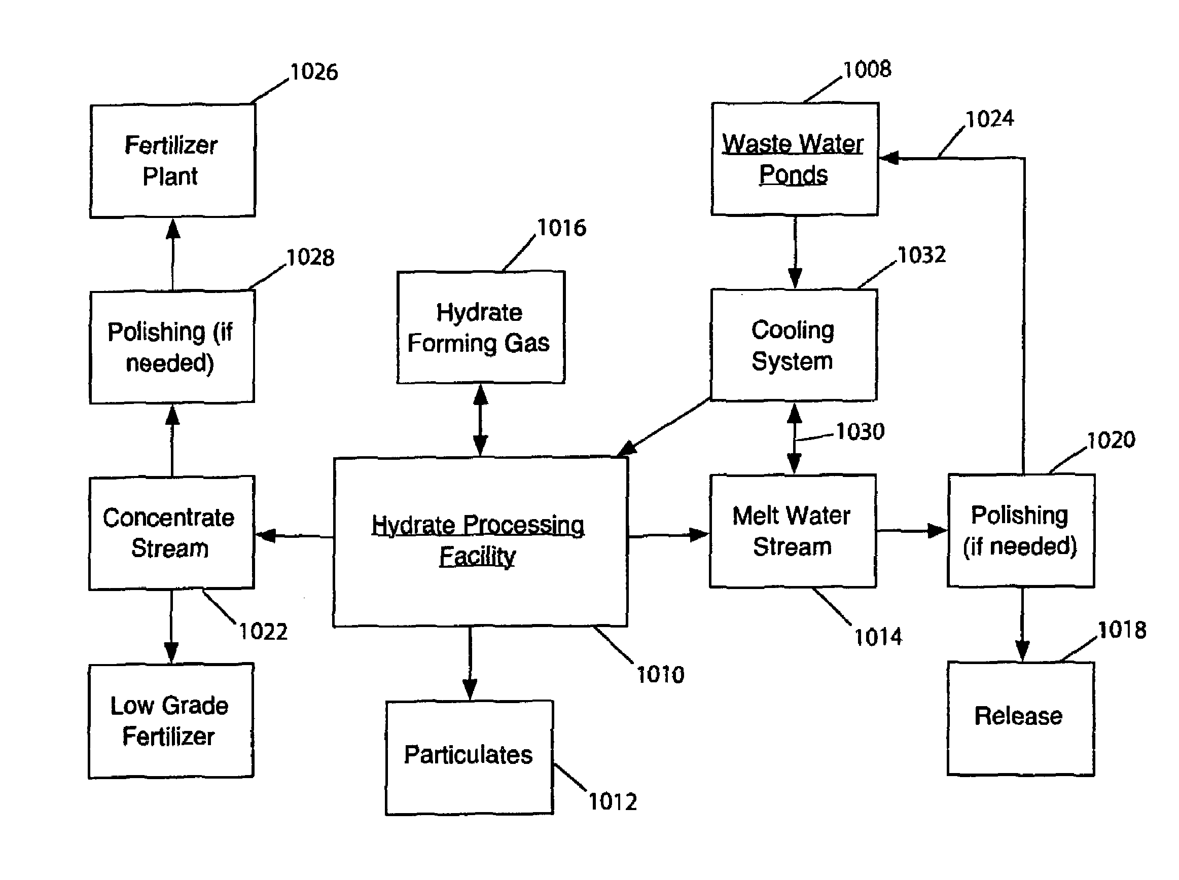
Hydrate-based reduction of fluid inventories and concentration of aqueous and other water-containing products

a technology of aqueous and other water-containing products and inventories, which is applied in the direction of differential sedimentation, solid separation, and calcium/strontium/barium sulfates, etc., can solve the problems of significant biodegradation and environmental impact, easy to destroy most aquatic organisms, and large so as to reduce the volume of waste water and reduce the volume of industrial waste water. , the effect of reducing the volume of industrial waste water

Inactive Publication Date: 2007-08-14
WATER REGENERATION SYST +1
View PDF85 Cites 18 Cited by
  • Summary
  • Abstract
  • Description
  • Claims
  • Application Information

AI Technical Summary

Benefits of technology

This method efficiently reduces water volume while providing a cost-effective and environmentally friendly solution by extracting fresh water and concentrating residual brine for industrial reuse, minimizing environmental hazards and operational costs.

Problems solved by technology

However, in a year where rainfall is significantly above average or where water management practices fail to sufficiently reduce water inventory, it may become necessary to treat the surplus water and release it to the surface waters in order to avoid an uncontrolled discharge of the untreated process water.
Unfortunately, the residual dissolved salts in industrial pond water present hazards to public health and the environment, and a significant release of pond water can easily destroy most aquatic organisms.
Although a significant emergency release of treated water may not have such severe results, it can still cause significant biodegradation and environmental impact.
Where ponds have a very large surface area, considerable evaporation may occur.
Further, high humidity, as often exists in Florida, lowers the rate of evaporation; when humidity approaches 100%, little evaporation takes place at all.
Artificial evaporation desalination techniques, such as multi-stage flash techniques, have substantial associated energy costs for heating the pond water (to make the process more efficient in terms of the percentage of water that can be evaporated from a particular volume of water).
In addition, because the untreated pond water may be at or close to saturation, evaporation will lead to the formation of large amounts of crystallized scale, which can clog the installation apparatus and render the process less efficient.
Thus, application of artificial evaporation desalination techniques appears to be impractical, without prior treatment to lower the pH by causing substantial precipitation of dissolved and suspended matter.
RO has a number of well-known limitations, especially in highly saline water and with dissolved solids at or near their saturation limit.
A significant limitation with RO treatment of highly saline or highly chemically saturated water is membrane fouling from suspended particulates and scaling.
Cooling the water or raising the concentration by removing water initiates precipitation of dissolved materials, and scaling of the RO membranes will result.
However, this method is very energy-intensive, especially if rapid freezing and subsequent melting is required, in part because the high volume of dissolved solids lowers the freezing point substantially.
Also, rapid freezing causes poor rejection of dissolved solids, which can be accommodated within the hexagonal crystal structure of ice.
Additionally, residual brines can be overgrown and trapped between ice crystals.
Furthermore, in a hot and humid region such as Florida, pond water freezing would be prohibitively expensive.
In the case of dairy and other food products, heat is commonly applied under partial vacuum conditions to lower the boiling point; otherwise, the food will be spoiled, which would require its disposal, or it will have an undesirable cooked flavor.
Thus, if reduced pressure is used, the vacuum need not be so deep, and hence as expensive to produce, but the amount of heat that has to be applied is greater.
Evaporation thus becomes less efficient under conditions of increasing concentration.
Because of the requirement to apply considerable heat over short periods of time, and often under conditions where vacuum pumping must be carried out continuously, present concentration processes add significant cost to the concentrated food production process.
Moreover, the efficiency of the process can decrease significantly with increasing concentration, as noted above.

Method used


Image

  • Hydrate-based reduction of fluid inventories and concentration of aqueous and other water-containing products
  • Hydrate-based reduction of fluid inventories and concentration of aqueous and other water-containing products
  • Hydrate-based reduction of fluid inventories and concentration of aqueous and other water-containing products

Examples


embodiment 230

[0077]The embodiment 230 is simplified in that heat of formation of the hydrate is transferred to water surrounding the thermal equilibration column 132 within a “water jacket” defined between the walls of the column 132 and the shaft 136 in which the desalination fractionation column is constructed. To this end, the hydrate formation conduit preferably is made from fabricated (i.e., “sewn”) artificial fiber material, which is ideal because of its light weight and its potential for being used in an open weave that greatly facilitates thermal equilibration between residual saline water within the thermal equilibration column 132 and seawater circulating within the water jacket.

[0078]As is the case with the embodiment shown in FIG. 2, warmed water is pumped out of the system, this warmed water being water which has circulated within the water jacket. In contrast to the embodiment shown in FIG. 2, however, the intent of removing warmed water from the water jacket is not to remove so mu...

embodiment 430

[0081]Whereas the embodiments described so far utilize gas or mixtures of gas which form positively buoyant hydrates under appropriate temperature and pressure conditions, the versatility of hydrate-based desalination, purification, or other fluid treatment can be expanded greatly by adapting the methods and apparatus described above to accommodate negatively buoyant hydrates. An embodiment 430 of a hydrate fractionation “column” configured to permit the use of negatively buoyant hydrate for water purification is shown in FIGS. 8-10. The major difference between this embodiment 430 and the preceding embodiments of hydrate fractionation columns is that the heat exchange and dissociation portion 350 of the installation is laterally or horizontally displaced or offset relative to the hydrate formation and heat removal sections 336 and 346, respectively. The hydrate formation and heat removal sections are similar to those in the embodiments described above.

[0082]A number of different op...

embodiment 600

[0114]An embodiment 600 in which dissociation and gas capture and processing are controlled so as to be kept at elevated pressure is illustrated in FIG. 15. In this embodiment, a physical barrier 610 extends across the fractionation column and blocks the upward movement of the hydrate slurry. The location of the barrier 610 depends on the stability limits of the particular hydrate-forming substance used, but will be above the region of hydrate stability (i.e., at lesser pressure-depth). As the hydrate dissociates, the released gas forms a pocket at trap 620 and enters a gas recovery and processing system 626 while still at a pressure depth considerably greater than one atmosphere surface pressure. (The gas processing system 626 may contain means for liquefying certain gases.) The gas is processed and re-injected into the hydrate formation section 628 at 629 in the same manner as in the previously described embodiments, except the gas system is maintained at considerably higher press...


PUM

PropertyMeasurementUnit
pHaaaaaaaaaa
pHaaaaaaaaaa
humidityaaaaaaaaaa

Abstract

Toxic waste waters polluted with high levels of chemical byproducts of various industrial processes (e.g., waste water held in industrial holding ponds) are treated using gas hydrate to extract and remove fresh water from the polluted water, thus reducing the volume of toxic waste water inventories. Extracting fresh water by forming and removing the hydrate raises the concentration of dissolved materials in the residual concentrated brines to levels at which the residual fluid is suitable for use as an industrial feedstock. Furthermore, so raising the concentration of the residual brine will cause certain mineral species to precipitate out of solution, which mineral species are separated from the fluid and may be put to other uses, as appropriate. Food products are also advantageously concentrated by means of gas hydrates.

Description

CROSS-REFERENCE TO RELATED APPLICATIONS[0001]This application is a divisional of U.S. application Ser. No. 10 / 833,175 filed Apr. 28, 2004, now abandoned, which is a continuation-in-part of U.S. application Ser. No. 10 / 266,258 filed Oct. 8, 2002 (issued May 11, 2004 as U.S. Pat. No. 6,733,667). That application is a divisional of U.S. application Ser. No. 09 / 397,500 filed Sep. 17, 1999 (issued Dec. 24, 2002 as U.S. Pat. No. 6,497,794), which is a continuation-in-part of U.S. application Ser. No. 09 / 375,410 filed Aug. 17, 1999 (issued Mar. 11, 2003 as U.S. Pat. No. 6,531,034), which is a continuation-in-part of U.S. application Ser. No. 09 / 350,906 filed on Jul. 12, 1999 (issued May 20, 2003 as U.S. Pat. No. 6,565,715).STATEMENT REGARDING FEDERALLY SPONSORED RESEARCH AND DEVELOPMENT[0002]This invention was made with Government support under Contract No. NBCHC 010003 dated Jan. 29, 2001 and issued by the Department of the Interior—National Business Center (DARPA). The Government has cer...

Claims


Application Information

Patent Timeline
Patent Type & Authority Patents(United States)
IPC IPC(8): C02F1/00B01D53/62C02F1/20C02F1/22C02F1/26C02F1/52
CPCA23L2/08B01D53/62C01F11/46C02F1/20C02F1/22C02F1/26C02F1/265B01D2257/504C02F1/5236C02F2101/101C02F2101/105C02F2103/18C02F2103/32Y02C10/04Y10S210/906Y02A20/124Y02C20/40Y02P20/151
Inventor MAX, MICHAEL D.OSEGOVIC, JOHN P.
Owner WATER REGENERATION SYST
Learn More