Chemical mechanical polishing pad dresser

a technology of mechanical polishing and dressing pad, which is applied in the field of dressing or conditioning the device and conditioning the chemical mechanical polishing pad, can solve the problems of the pad dresser, the accumulation of polishing debris coming from the workpiece, and the inability of the pad surface to hold the abrasive particles of the slurry,

Active Publication Date: 2007-08-21
KINIK
View PDF9 Cites 66 Cited by
  • Summary
  • Abstract
  • Description
  • Claims
  • Application Information

AI Technical Summary

Benefits of technology

[0009]Accordingly, the present invention provides CMP pad dressers and methods that are suitable to groom the CMP pads used for the delicate polishing applications as recited above. In one aspect, such a CMP pad dresser may include a resin layer, and a superabrasive grit held in the resin layer. It has been discovered that retention of the superabrasive particles in the resin layer may be improved by disposing a metal coating layer between at least a portion of each superabrasive grit and the resin layer as compared to superabrasive grit absent such a metal coating layer. An exposed portion of the superabrasive grit can protrude at least partially from the resin layer, and can protrude substantially to a predetermined height. The metal coating layer can extend substantially along each superabrasive grit and resin layer interface, and the protruding portion of the superabrasive grit can be substantially free of the metal coating layer. Furthermore, the metal coating layer can be chemically bonded to at least a portion of each superabrasive grit, and the metal coating layer can in turn, be mechanically bonded to at least a portion of the resin layer.
[0010]The present invention additionally encompasses methods of improving retention of superabrasive grit held according to a predetermined pattern in a solidified resin layer. Such methods may include disposing a metal coating layer between at least a portion of each superabrasive grit and the resin layer such that each superabrasive grit includes an exposed portion that protrudes at least partially from the resin layer. The exposed portion may be substantially free of the metal coating layer. The metal coating layer may have a surface that provides increased mechanical bonding with the resin layer.

Problems solved by technology

One problem that arises with regard to maintaining the pad surface, however, is an accumulation of polishing debris coming from the work piece, the abrasive slurry, and the pad dresser.
This accumulation causes a “glazing” or hardening of the top of the pad, mats the fibers down, and thus makes the pad surface less able to hold the abrasive particles of the slurry.
These effects significantly decrease the pad's overall polishing performance.
Further, with many pads, the pores used to hold the slurry, become clogged, and the overall asperity of the pad's polishing surface becomes depressed and matted.
In addition to the tremendous density issues that already exist, with the current movement toward size reduction, ULSI has become even more delicate, both in size and materials than ever before.
There are a number of problems in attempting to provide such a pad dresser.
Generally speaking, the superabrasive particles are so small that a traditional metal matrix is often unsuitable for holding and retaining them.
However, such a variation would render a dresser useless if it were required to dress a CMP pad and achieve a uniform asperity depth of 20 μm or less, for example.
In addition to issues with properly holding very small superabrasive particles, the tendencies of metal to warp and buckle during a heating process, cause additional issues in obtaining a CMP pad dresser having superabrasive particle tips leveled to within a narrow tolerance range.
While other substrate materials such as polymeric resins have been know, such materials typically are not able to retain superabrasive particles to a degree that is sufficient for CMP pad dressing.

Method used


Image

  • Chemical mechanical polishing pad dresser
  • Chemical mechanical polishing pad dresser
  • Chemical mechanical polishing pad dresser

Examples


example 1

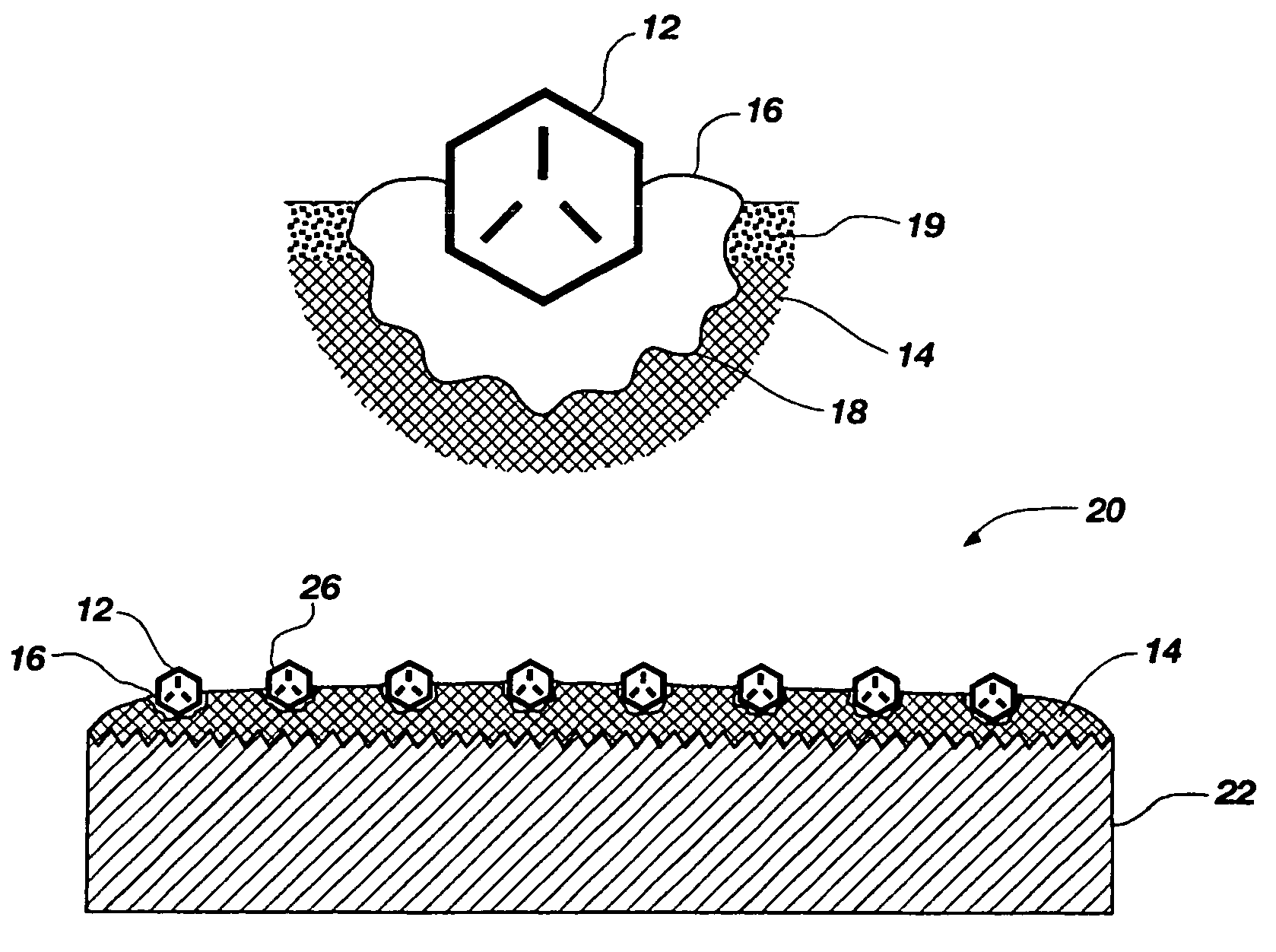
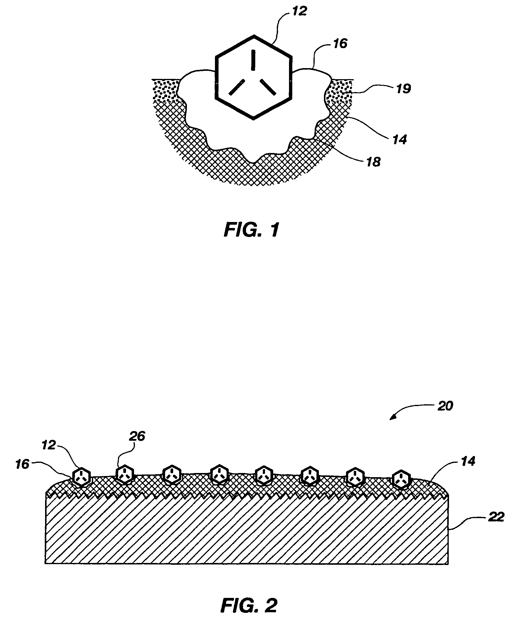
[0068]Diamond grit having an average size of about 65 microns are coated with nickel by an electroless process (with hypophosphate reducing agent) to form a spiky exterior of about 130 microns. The coated diamond grit are arranged with a template to stick on a 100 mm diameter, 10 mm thick flat base plate. The coated diamond grit form a grid pattern with an inter-diamond pitch of 500 microns. The plate is placed at the bottom of a steel mold and covered with a polyimide resin powder. Subsequently, the entire assembly is pressed to 50 MPa pressure and 350° C. for 10 minutes. The polyimide consolidated plate is 7 mm thick with nickel coated diamond grit forming a grid on one side. A conventional grinding wheel with silicon carbide grit is used to grind the surface to expose the nickel coated diamond to about 60 microns. Subsequently, an aqua regia solution is used to dissolve the remaining nickel that is exposed above the polyimide resin surface. The final product is a pad conditioner ...

example 2

[0069]The same procedure is followed as Example 1, however a phenolic resin is used in place of the polyimide resin, and the forming temperature is reduced to 200° C.

example 3

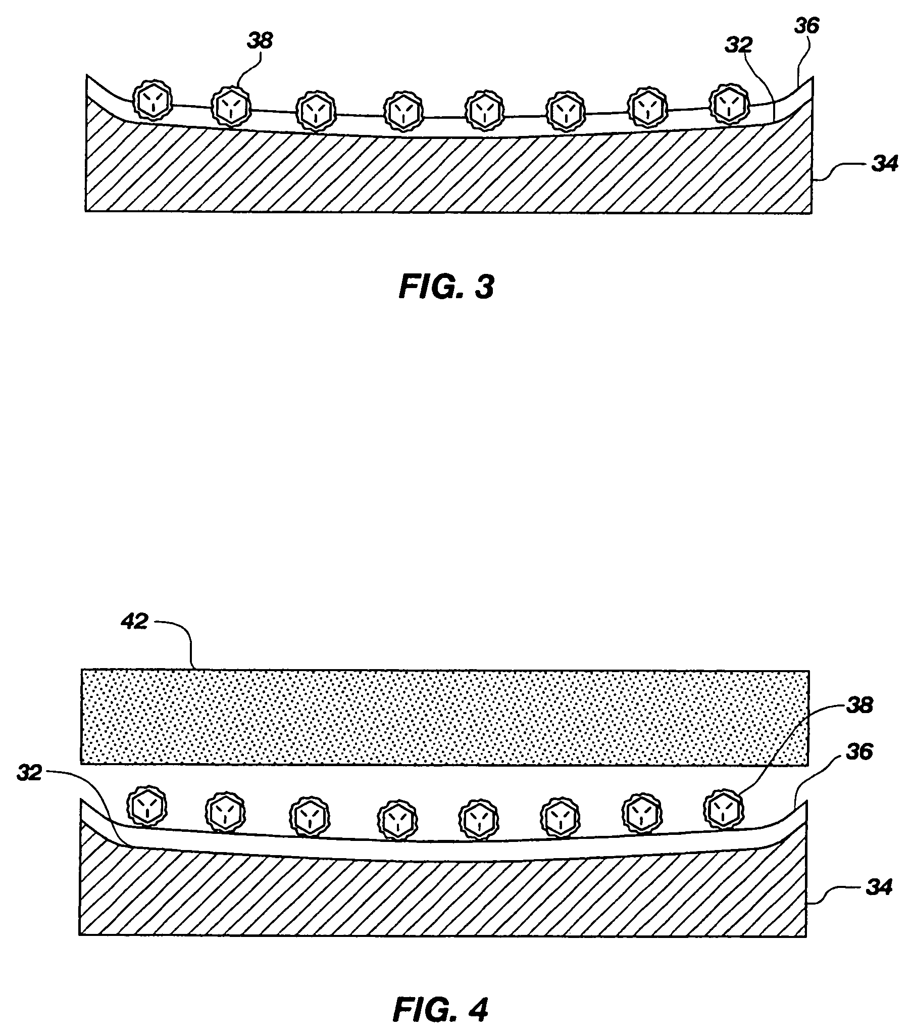
[0070]The same procedure is followed as Example 1, however the base plate is precoated with a layer of clay that is about 60 microns thick. After hot pressing, the clay is scraped off, exposing the nickel coated diamond protruding from the polyimide resin layer. The diamond is then exposed by etching the nickel with acid.


PUM

PropertyMeasurementUnit
sizeaaaaaaaaaa
sizeaaaaaaaaaa
heightaaaaaaaaaa

Abstract

CMP pad dressers and their methods of manufacture are disclosed. One aspect of the present invention provides a CMP pad dresser having improved superabrasive grit retention in a resin layer. The CMP pad includes a resin layer, superabrasive grit held in the resin layer such that an exposed portion of each superabrasive grit protrudes from the resin layer, and a metal coating layer disposed between each superabrasive grit and the resin layer, where the exposed portions are substantially free of the metal coating layer. The metal coating layer acts to increase the retention of the superabrasive grit in the resin layer as compared to superabrasive grit absent the metal coating layer.

Description

FIELD OF THE INVENTION[0001]The present invention relates generally to a device and methods for dressing or conditioning a chemical mechanical polishing (CMP) pad. Accordingly, the present invention involves the chemical and material science fields.BACKGROUND OF THE INVENTION[0002]Many industries utilize a chemical mechanical polishing (CMP) process for polishing certain work pieces. Particularly, the computer manufacturing industry relies heavily on CMP processes for polishing wafers of ceramics, silicon, glass, quartz, and metals. Such polishing processes generally entail applying the wafer against a rotating pad made from a durable organic substance such as polyurethane. A chemical slurry is utilized that contains a chemical capable of breaking down the wafer substance and an amount of abrasive particles which act to physically erode the wafer surface. The slurry is continually added to the rotating CMP pad, and the dual chemical and mechanical forces exerted on the wafer cause i...

Claims


Application Information

Patent Timeline
Patent Type & Authority Patents(United States)
IPC IPC(8): B24D3/00B24B21/00B24D11/00B24D18/00B24D99/00
CPCB24B1/00B24B53/02B24B53/10B24B53/12B24D3/00B24D11/00C09K3/14
Inventor SUNG, CHIEN-MIN
Owner KINIK
Why Eureka
Try Eureka