Ultra wide bandwidth communications method and system

a communication method and wide-band technology, applied in the field of radio communication transmitters, can solve the problems of too much interference to the communication system, easy blockage of energy, interference on the part of other users, etc., and achieve the effect of increasing the data rate, speed and performance of logic circuitry, and increasing the efficiencies of communication

Inactive Publication Date: 2007-10-09
NORTH STAR INNOVATIONS
View PDF10 Cites 82 Cited by
  • Summary
  • Abstract
  • Description
  • Claims
  • Application Information

AI Technical Summary

Benefits of technology

[0038]It is another object of the present invention to communicate one or more bits per wavelet by constructing each wavelet from a family of master wavelet shapes. It is an object of the present invention to convey information by allowing the wavelet coefficients (e.g. the ai and bi) to vary between +1 and −1 such that inverted or non-inverted copies of a family of wave-shapes are transmitted and received.
[0041]It is also an object of the present invention to exploit multipath effects to enhanced UWB signal reception.
[0045]Moreover, a feature of the present invention is that as new semiconductor circuitry is introduced, according to Gordon Moore's hypothesis that processing power will double approximately every eighteen months, the communications efficiencies of the present invention also increase according to “Moore's law”.
[0046]Moreover, the present invention produces waveforms based on rise and fall times (edges) of logic circuitry. Thus, as the speed and performance of logic circuitry increases with time, so does the bandwidth available for transmission according to the present invention, thereby allowing increase in data rate based on a power spectral density limited channel, to be implemented according to the present invention.

Problems solved by technology

However, when the transmitted energy is concentrated at such high frequencies, the energy is easily blocked by terrain or other intervening objects that are present between the transmitter and the receiver.
Too much interference is impinged on the other users, who themselves cause too much interference to the communication system.
Typically, high-speed links operate on microwave carriers that are easily blocked by terrain and intervening objects.
In contrast, conventional systems typically have less than 10% bandwidth, and therefore have poor resolution at low frequencies.
As presently recognized, this low duty cycle causes two problems.
First, it is difficult, or nearly impossible, to generate significant average power efficiently due to high peaks.
For example, because the peak voltages are higher than breakdown voltage of state-of-the-art components, low-voltage (1.8 V) CMOS in bipolar processes, standard low cost implementations are limited.
Second, the high peaks disrupt “crystal detector” receivers, which are sensitive to time-domain space.
Low voltage parts can easily create the required waveforms, and the transmitted energy is spread in both time and frequency so that it looks like noise in all domains.
Consequently, it takes more signal power to get over the noise.
Conventional systems are limited by intersymbol interference caused by multipath.
Buildings, for example, give rise to particularly bad multipath (i.e., interfering echo signals) occurring out to about 500 ns after the direct path signal.
The multipath degradation described earlier, however, would be severely aggravated, plus the other problems accentuated too.
Conventional UWB systems lack control over the shape of their waveform, and are unable to transmit multiple bits per pulse.
This reduces the realized data rate and makes the devices difficult to use.

Method used


Image

  • Ultra wide bandwidth communications method and system
  • Ultra wide bandwidth communications method and system
  • Ultra wide bandwidth communications method and system

Examples


Embodiment Construction

[0112]Preferred embodiments of the present invention will now be described with reference to the drawings. Throughout the several views, like reference numerals designate identical or corresponding parts.

Defining UWB

[0113]From an energy spreading perspective, or from a resolution perspective, bandwidth and center frequency can be treated independently. However, the term “relative bandwidth” is helpful in defining ultra wide bandwidth (UWB) transmissions.

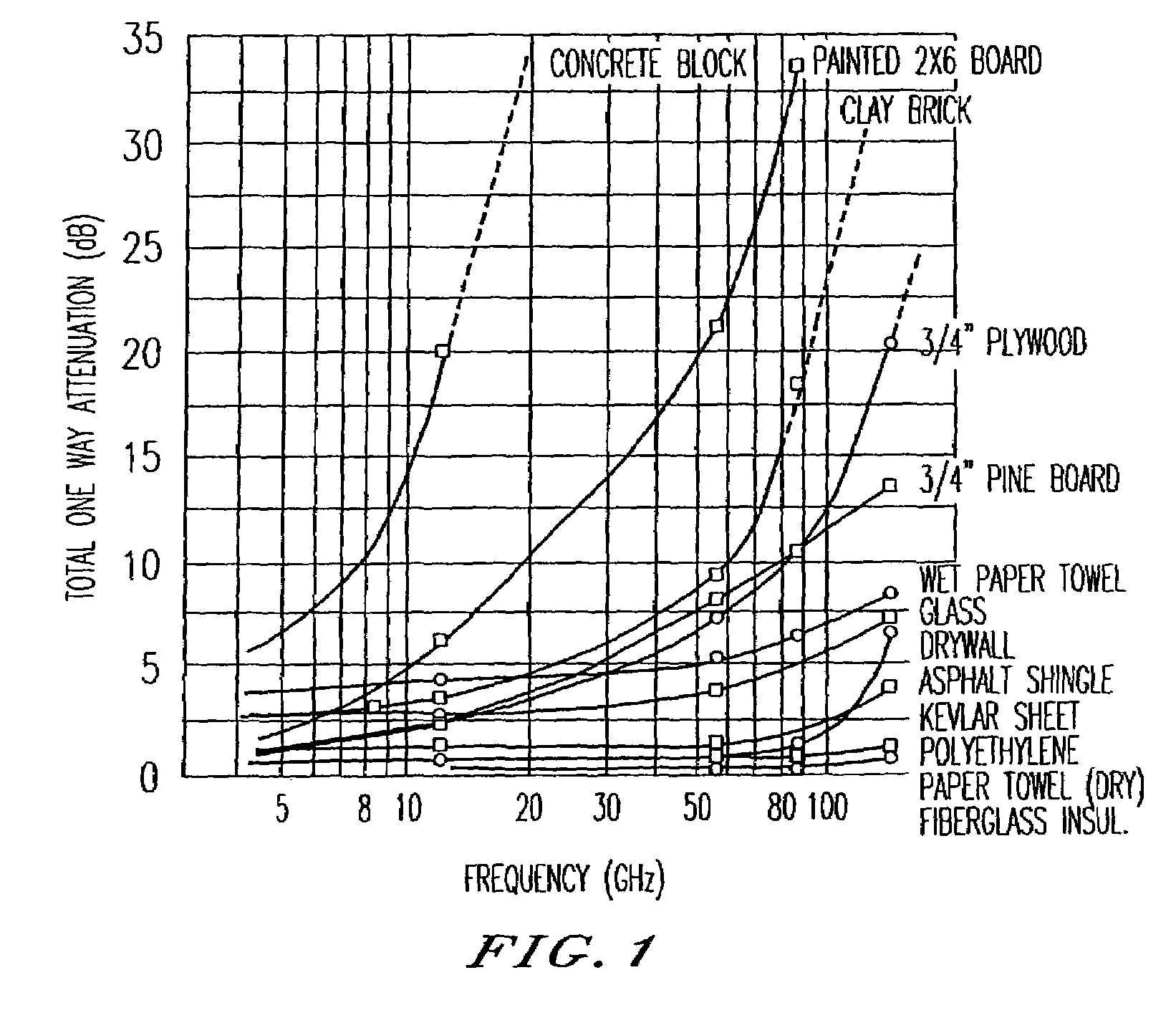
[0114]As recognized by the present inventors, the motivations for preferring definitions based on bandwidth relative to center frequency follow from three primary desirable features. The first is immunity to scintillation and multipath fading. The only way to prevent scintillation, speckle, and multipath fading is to have resolution that is approximately equal to the wavelength. The second is penetrating materials with high bandwidth signals. To communicate at the highest data rates through lossy media, or to do the highest resolutio...


PUM


Abstract

An ultra wide bandwidth, high speed, spread spectrum communications system uses short wavelets of electromagnetic energy to transmit information through objects such as walls or earth. The communication system uses baseband codes formed from time shifted and inverted wavelets to encode data on a RF signal. Typical wavelet pulse durations are on the order of 100 to 1000 picoseconds with a bandwidth of approximately 8 GHz to 1 GHz, respectively. The combination of short duration wavelets and encoding techniques are used to spread the signal energy over a an ultra wide frequency band such that the energy is not concentrated in any particular narrow band (e.g. VHF: 30-300 MHz or UHF: 300-1000 MHz) and is not detected by conventional narrow band receivers so it does not interfere with those communication systems. The use of pulse codes composed of time shifted and inverted wavelets gives the system according to the present invention has a spatial resolution on the order of 1 foot which is sufficient to minimize the negative effects of multipath interference and permit time domain rake processing.

Description

CROSS-REFERENCE TO RELATED PATENT DOCUMENTS[0001]This application is a continuation-in-part of commonly owned, application Ser. No. 09 / 209,460, filed Dec. 11, 1998, entitled ULTRA WIDE BANDWIDTH SPREAD-SPECTRUM COMMUNICATIONS SYSTEM, now issued as U.S. Pat. No. 6,700,939, which claims priority to provisional application Ser. No. 60 / 069,594, filed Dec. 12, 1997, entitled ULTRA WIDE BANDWIDTH (UWB) SPREAD-SPECTRUM DIGITAL COMMUNICATIONS SYSTEM. This application is also a continuation-in-part of commonly owned, application Ser. No., 09 / 684,782, filed Oct. 10, 2000, entitled ULTRA WIDEBAND COMMUNICATION SYSTEM, METHOD, AND DEVICE WITH LOW NOISE RECEPTION, now issued as U.S. Pat. No. 6,859,506, which claims priority to provisional application Ser. No. 60 / 207,225, filed May 26, 2000, entitled ULTRA WIDEBAND COMMUNICATIONS SYSTEM AND METHOD, and provisional application Ser. No. 60 / 217,099, filed Jul. 10, 2000, entitled MULTIMEDIA WIRELESS PERSONAL AREA SYSTEM NETWORK (WPAN) PHYSICAL LAYER ...

Claims


Application Information

Patent Timeline
Patent Type & Authority Patents(United States)
IPC IPC(8): H04L27/04G01S13/02H04B1/69H04B1/74H04L25/49H04L27/00
CPCG01S7/023G01S13/0209H04B1/69H04L27/0004H04B1/74H04L25/4902H04B1/7174H04B1/7183
Inventor MCCORKLE, JOHN W.ROFHEART, MARTIN
Owner NORTH STAR INNOVATIONS
Why Eureka
Try Eureka