
Low platinum fuel cell catalysts and method for preparing the same

a fuel cell and platinum technology, applied in the field of electrochemical catalysts, can solve the problems of low catalyst efficiency, low catalyst efficiency, and inability to develop early scientific experiments into commercially viable industrial products, etc., and achieve the effects of enhancing gas dispersion, high catalyst efficiency, and large surface area

Inactive Publication Date: 2008-04-01
INTEMATIX
View PDF79 Cites 66 Cited by
  • Summary
  • Abstract
  • Description
  • Claims
  • Application Information

AI Technical Summary

Benefits of technology

[0076]In a more traditional configuration (see, e.g., “A” in FIG. 14), the catalyst (nanoparticles coated with a thin film) forms a separate layer on the electrode or on a polymer membrane. In addition, a microdiffusion layer can optionally be present. Such a configuration thus comprises seven discrete layers (two electrodes, two catalyst layers, two microdiffusion layers, and a PEM). It is a surprising discovery and advantage of the present invention however, that the nanoparticles can interleave with the fibers comprising a gas-diffusable electrode (e.g. a carbon fiber sheet) and thus the fuel cell catalyst (thin-film coated nanoparticles) can be fabricated so that they are integral with the electrode. In addition the nanoparticles catalyst is itself capable of acting as a microdiffusion layer, so no additional microdiffusion layer is necessary or desired. Thus, in certain embodiments, this invention contemplates a integrated gas-diffusion / electrode / catalyst (IGEC) and membrane combination comprising only three layers; e.g., two IGEC layers separated by a proton exchange membrane (see, e.g., “B” in FIG. 14).
[0077]Such an integrated microdiffusion layer and catalyst / carbon layer can be readily fabricated. For example, carbon nanotubes (CNT) can be directly grown on carbon fibers on the surface layer (1-5 fiber diameter) carbon fiber sheet (see, e.g., FIG. 10). The bare carbon fiber diameter is about 10 μm (see, e.g., FIG. 11, panel 1) and the CNT covered carbon diameter is about 50 μm (see, e.g., FIG. 13, panel B). The large pores of the gas diffusion electrode are thus converted into small pores and the CNT covered top carbon fiber layer can act as a microdiffusion layer enhancing the dispersion of gas (e.g. hydrogen) to the catalyst. The platinum or alloy thin film coating on top of the carbon nanotubes acts as an efficient catalyst structure with large surface area.
[0078]In an alternative approach nanoparticles (e.g. CNTs, CNHs, or other nanopowders) can be sprayed, on carbon fiber sheet (or other gas diffusion electrodes) and the thin film is then coated on the nanoparticle layer. An intermediate microdiffusion layer can, optionally, be used between the nanoparticle / catalyst layer and carbon fiber sheet (gas diffusion electrode), e.g. as shown in FIG. 12.
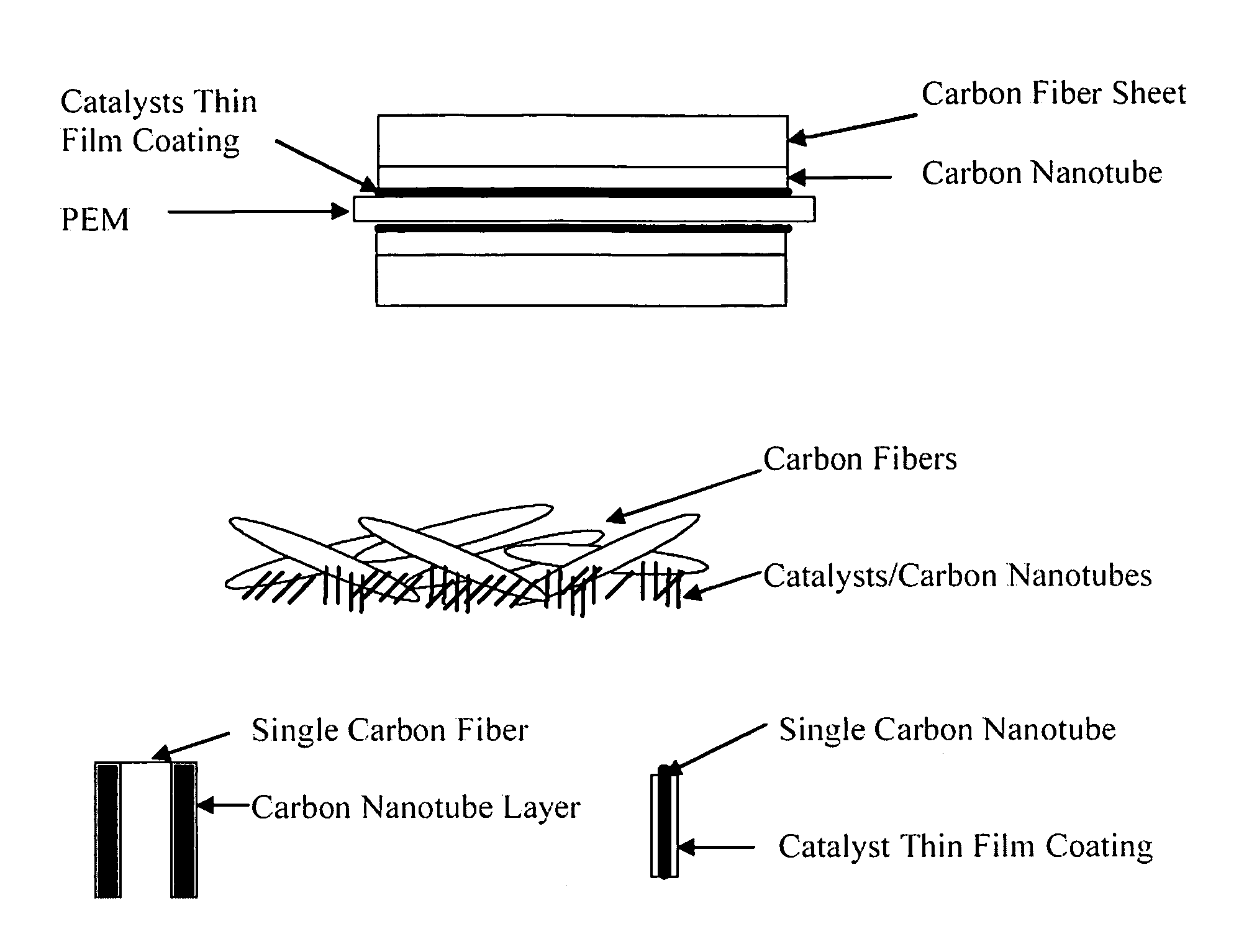
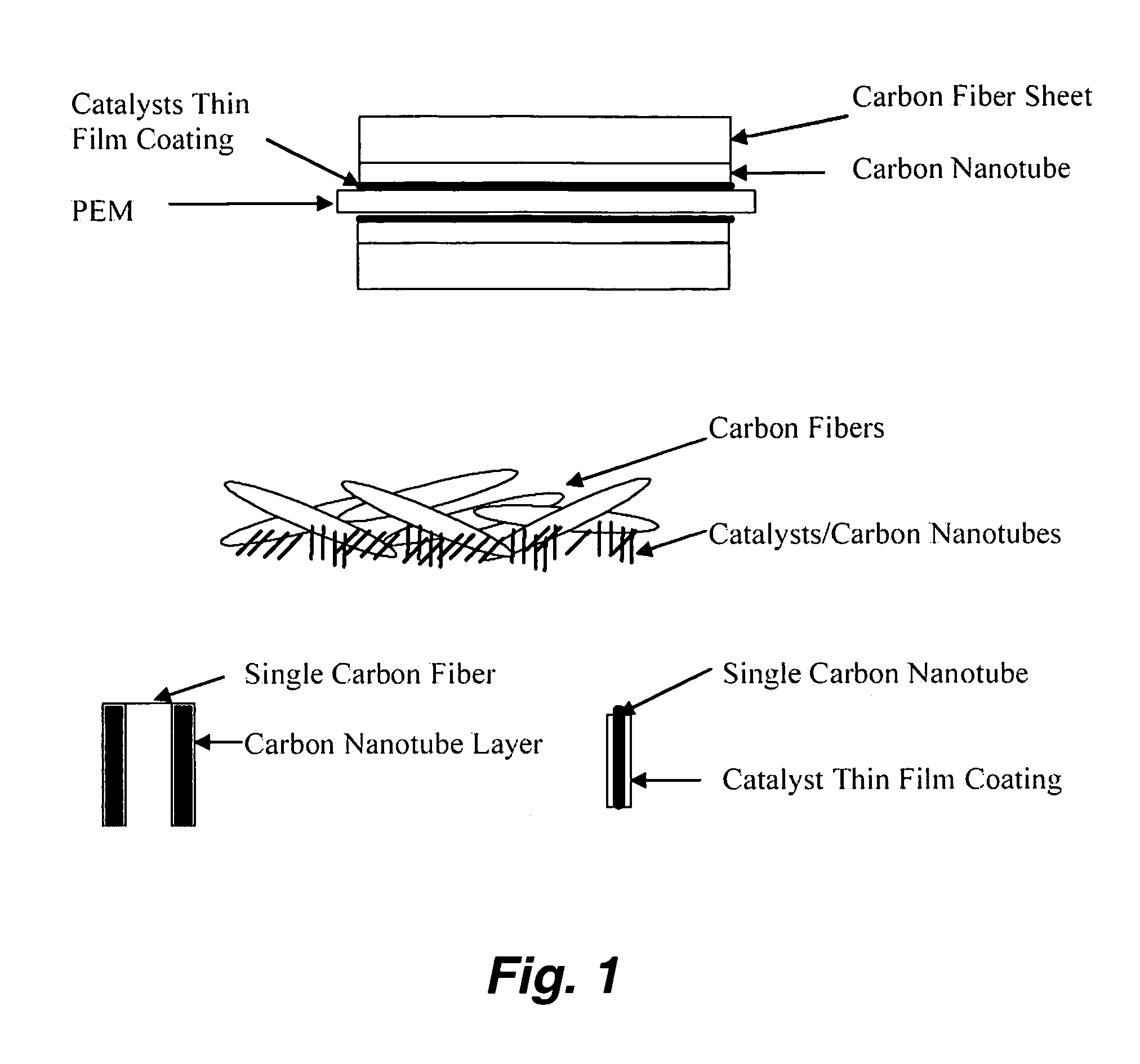
[0079]In certain embodiments, fibers or whiskers made of carbon, and / or other electrical conducting materials, are grown up on porous electrical conducting substrates. They can be used as a support for the catalytic thin film. In one preferred approach carbon nanotubes are directly grown on a commercial carbon fiber paper; then a thin layer of catalyst of, e.g., Pt, Ni, Co, Fe and their alloys are deposited by chemical vapor deposition on the carbon nanotubes as shown schematically in FIG. 1. Carbon nanotubes or other similar electrical conducting nanostructured materials can also be sprayed or brushed on carbon fiber paper (gas diffusion) electrodes. Platinum alloy thin film catalysts can then be deposited on these carbon nanotube layers which directly contact a proton exchange membrane (PEM).
[0080]In certain embodiments, carbon nanotubes or other similar electrical conducting nanostructured materials can also be prepared as a thin sheet with an optimized porosity and preferred thickness e.g., of a few nanometers to tens of micrometers. The thin sheet is then placed or pressed on carbon fiber paper. The thin film catalysts can then be deposited on the carbon nanotube sheet which directly contacts the proton exchange membrane.
[0081]In certain preferred embodiments, each carbon nanoparticles (e.g. carbon nanotube) is coated with the thin film catalysts first. For example electroplating can be used to fabricate such catalyst-coated carbon nanotubes or other similar electrical conducting nanostructured materials. Then these catalyst-coated electrical conducting nanostructured materials can then be sprayed, brushed or painted on the carbon paper electrodes or on fuel cell membrane layer. Alternatively these catalystcoated electrical conducting nanostructured materials can also be prepared as a thin sheet with an optimized porosity and preferred thickness of few to tens of micrometers. Such sheet will then placed or pressed on carbon fiber paper.

Problems solved by technology

Fuel cells have potential for stationary and portable power applications; however, the commercial viability of fuel cells for power generation in stationary and portable applications depends upon solving a number of manufacturing, cost, and durability problems.
However, in spite of the attractive system efficiencies and environmental benefits associated with fuel-cell technology, it has proven difficult to develop the early scientific experiments into commercially viable industrial products.
Problems have often been associated with lack of appropriate materials that would enable the cost and efficiency of electricity production to compete with existing power technology.
However, problems associated with the cost, activity, and stability of the electrocatalyst are major concerns in the development of the polymer electrolyte fuel cell.
Unfortunately, the high cost and scarcity of platinum has limited the use of this material in large-scale applications.
In addition poisoning at the anode by carbon monoxide has been a problematic with the use of platinum.
On the cathode side, usually more higher catalyst levels have been desired because methanol and other carbon containing fuel passing through the membrane react with oxygen on the cathode under catalytic effect of platinum thereby decreasing the efficiency of the full cell.
In these “ink” coating structure, the efficiency of the catalysts are still restricted by gas and proton diffusion.
However the process is complicated by non-electrical conducting nano polymer whiskers and transferring the catalyst coated polymer whisker layers onto carbon electrodes.

Method used


Image

  • Low platinum fuel cell catalysts and method for preparing the same
  • Low platinum fuel cell catalysts and method for preparing the same
  • Low platinum fuel cell catalysts and method for preparing the same

Examples


example 1

[0090]Pt alloy thin film catalysts were processed through multiplayer depositions and post diffusion annealing. For alloy films with a fixed composition the thickness ratio calculated from atomic weight of the selected elements will be used to control a desired composition. For alloy films with continuously changed composition, the thickness gradient profiles were generated during the deposition process. The ion beam sputtering depositions were carried out under a typical condition of 10−4 torr and room temperature with pure metal targets. Typical total thickness of multilayers is about 100 Å. Post annealing for inter-diffusion were carried out at 700° C. for 12 hours under 10−8 torr vacuum. The commercial carbon fiber papers were used as substrates for most of the composition studies.

[0091]The carbon nanotubes deposited on the carbon fiber papers were used for enhancing the catalyst surface area and providing a micro gas-diffusion structure. The growth procedures for carbon nanotub...


PUM

PropertyMeasurementUnit
widthaaaaaaaaaa
widthaaaaaaaaaa
diameteraaaaaaaaaa

Abstract

This invention provides novel fuel cell catalysts comprising new series of catalytically active thin-film metal alloys with low platinum concentration supported on nanostructured materials (nanoparticles). In certain embodiments, an integrated gas-diffusion / electrode / catalyst layer can be prepared by processing catalyst thin films and nanoparticales into gas-diffusion media such as Toray or SGL carbon fiber papers. The catalysts can be placed in contact with an electrolyte membrane for PEM fuel cell applications.

Description

CROSS-REFERENCE TO RELATED APPLICATIONS[0001]This application is related to provisional applications U.S. Ser. No. 60 / 549,712, filed on Mar. 2, 2004, and U.S. Ser. No. 60 / 501,158, filed on Sep. 8, 2003.STATEMENT AS TO RIGHTS TO INVENTIONS MADE UNDER FEDERALLY SPONSORED RESEARCH AND DEVELOPMENT[0002][Not Applicable]FIELD OF THE INVENTION[0003]This invention is in the field of electrochemical catalysts used in fuel cells (e.g., in polymer electrolyte membrane (PEM) fuel cells). The invention is related to the reduction of the platinum contents and the improvement of the catalytic efficiency by innovative catalyst compositions and nanostructures at the interfaces, or inside a gas micro distribution (microdiffusion) layer, between the electrodes and the polymer electrolyte (PEM) comprising the fuel cell.BACKGROUND OF THE INVENTION[0004]Fuel cells combine hydrogen and oxygen without combustion to form water and to produce direct current electric power. The process can be described as ele...

Claims


Application Information

Patent Timeline
Patent Type & Authority Patents(United States)
IPC IPC(8): H01M4/96B01J21/18H01M8/10B05D5/12H01M4/92B01J23/42H01B1/00H01B1/04H01M4/88H01M4/90
CPCB82Y30/00H01M4/92H01M4/921H01M4/926H01M8/0234H01M8/1002Y02E60/521H01M8/1007Y02E60/50
Inventor WANG, NINGDONG, YILI, YI-QUN
Owner INTEMATIX
Learn More