Semiconductor integrated circuit device
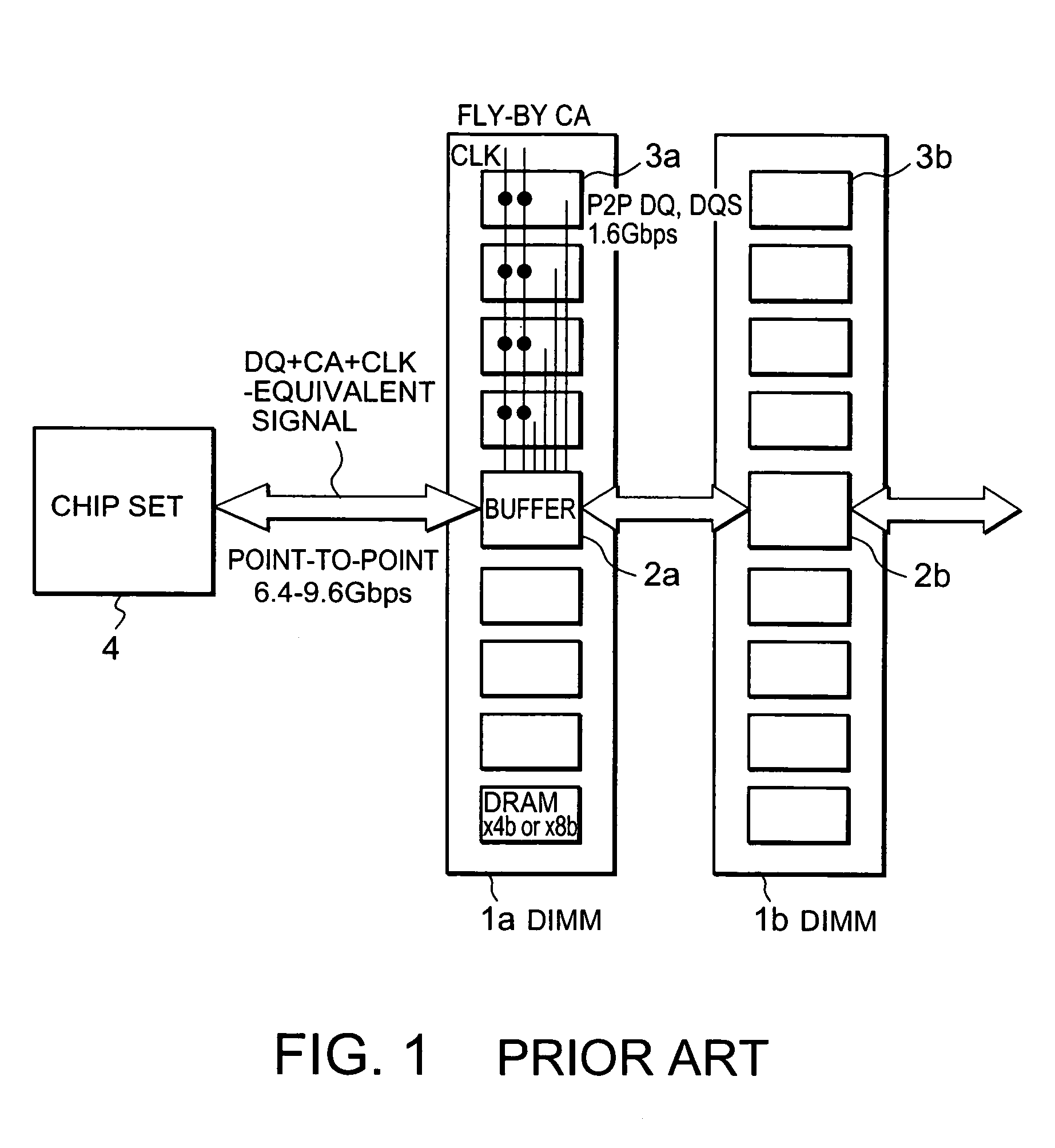
a technology of integrated circuits and semiconductors, applied in the direction of information storage, instruments, electric digital data processing, etc., can solve the problems of difficult direct connection between i/f lsi and pcb, and achieve the effect of reducing the number of terminating resistors, reducing the skew of each signal, and easy realization of impedance matching of each signal lin
- Summary
- Abstract
- Description
- Claims
- Application Information
AI Technical Summary
Benefits of technology
Problems solved by technology
Method used
Image
Examples
first embodiment
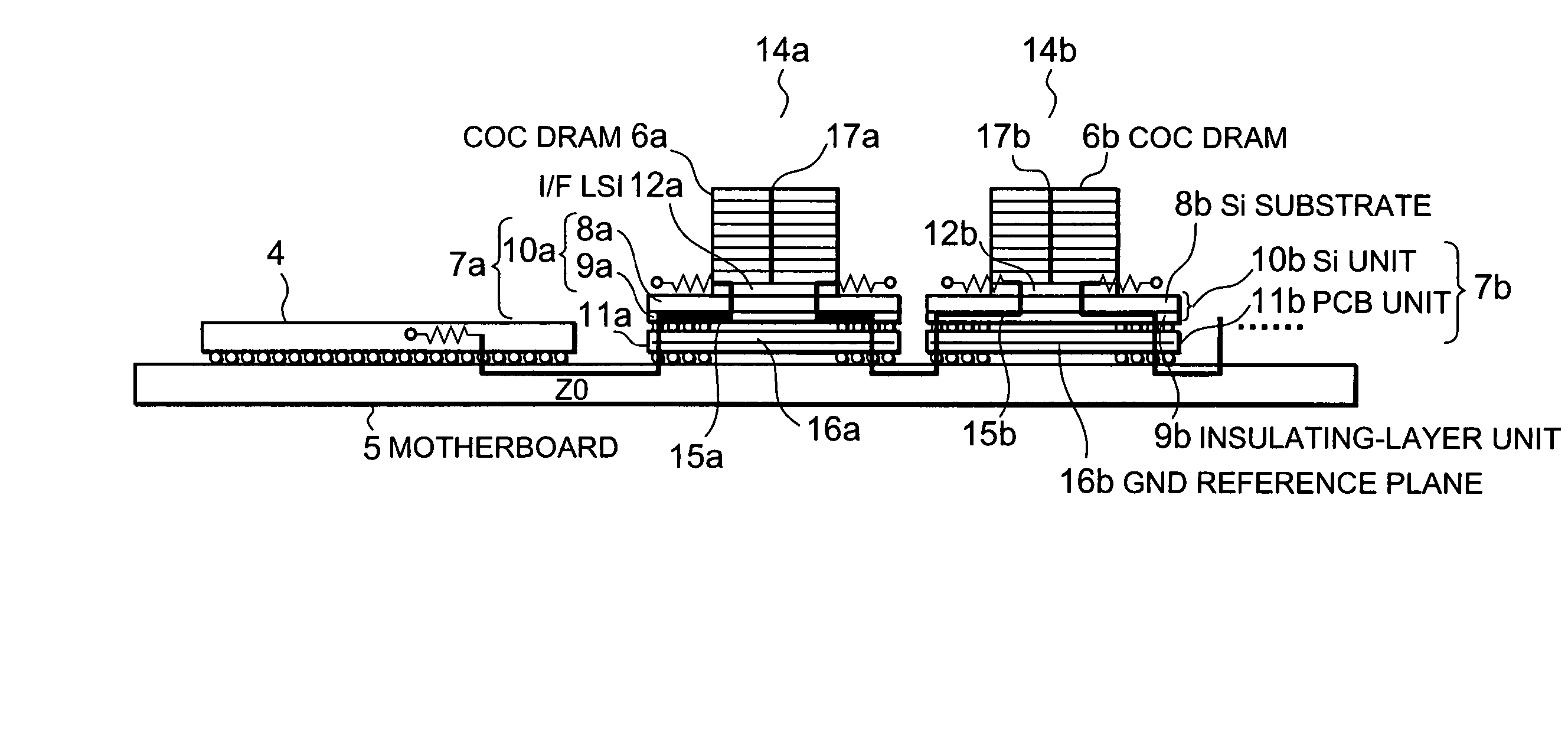
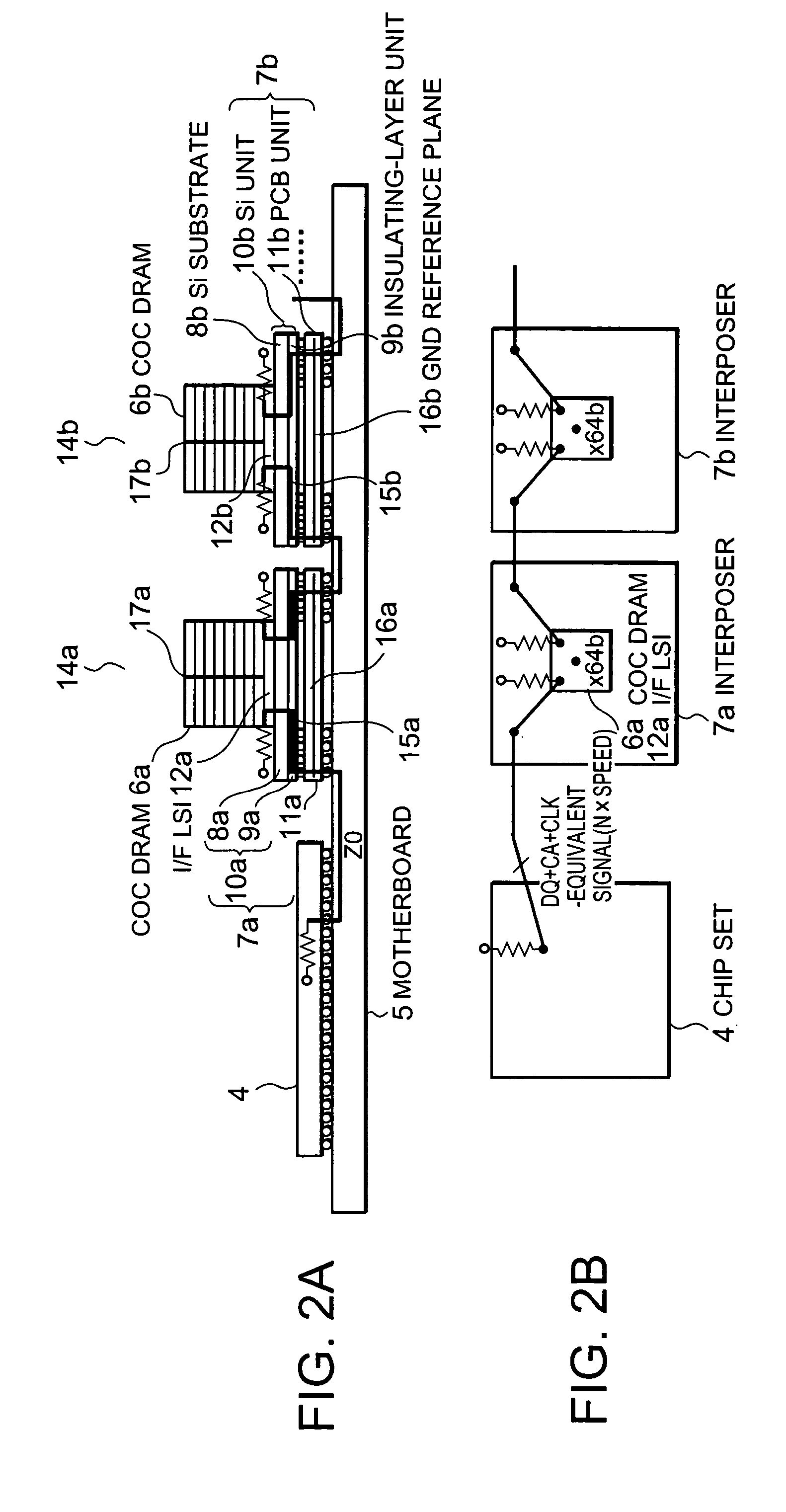
[0066]FIGS. 2A and 2B schematically show the configuration of a memory system (semiconductor integrated circuit (IC) device) according to the present invention, in which FIG. 2A is a longitudinal cross-sectional view and FIG. 2B is a plan view.
[0067]The memory system shown in FIGS. 2A and 2B includes a chip set 4 mounted on a motherboard 5 and a plurality of (two of them are shown here) stacked DRAMs 14a and 14b. Each of the stacked DRAMs 14a and 14b includes a chip on chip DRAM (COC DRAM) 6a (6b) including 8 to 16 stacked DRAM chips, an interface LSI (I / F LSI) 12a (12b) on which the COC DRAM 6a (6b) is stacked, and an interposer 7a (7b) which is disposed under the I / F LSI 12a (12b) and which includes a silicon (Si) unit 10a (10b) and a printed circuit board (PCB) 11a (11b).
[0068]The Si unit 10a (10b) of the interposer 7a (7b) includes a Si substrate 8a (8b) and an insulating-layer unit 9a (9b). The Si unit 10a (10b) and the PCB 11a (11b) of the interposer 7a (7b) are connected to e...
second embodiment
[0134]FIG. 8 is a schematic view showing the configuration of a memory system according to the present invention. In FIG. 8, parts which are the same as those in FIGS. 2A and 2B are denoted by the same reference numerals.
[0135]The basic configuration of the memory system according to the second embodiment is the same as that in the first embodiment. The difference between these embodiments is that coaxial compact high-frequency connectors 80 are used instead of solder balls for connecting the PCB 11 and the motherboard 5. By using the connectors, the high-speed performance can be further enhanced.
[0136]Next, a method for placing the I / F LSI 12, which is common to the memory systems according to the first and second embodiments, will be explained with reference to FIGS. 9A and 9B.
[0137]As will be understood from FIGS. 9A and 9B, when the number of signals 85 (in this case, 1) input / output to / from the I / F LSI 12 through its lower surface is different from the number of signals 86 (in ...
third embodiment
[0147]Next, a memory system according to the present invention will be described with reference to FIGS. 11A and 11B. In FIGS. 11A and 11B, parts which are the same as those in FIGS. 2A and 2B are denoted by the same reference numerals.
[0148]The difference between the memory system shown in FIGS. 11A and 11B and that in FIGS. 2A and 2B is that each of stacked DRAMs 100 does not include the I / F LSI 12 and that a chip set 102 and the stacked DRAMs 100 are connected by a kind of point-to-point connection (one to plurality connection). That is, in the memory system according to the third embodiment, each of the stacked DRAMs 100 includes the COC DRAM 6 and the interposer 7, and a corresponding ball of all the stacked DRAM 100 is connected to each ball under the chip set 102. The chip set 102 and the COC DRAM 6 directly transmit / receive signals without using the I / F LSI 12.
[0149]The characteristic impedance of each signal line for connecting the chip set 102 and the stacked DRAM 100 is s...
PUM
 Abstract
Description
Claims
Application Information
 - R&D
- Intellectual Property
- Life Sciences
- Materials
- Tech Scout
- Unparalleled Data Quality
- Higher Quality Content
- 60% Fewer Hallucinations
Browse by: Latest US Patents, China's latest patents, Technical Efficacy Thesaurus, Application Domain, Technology Topic, Popular Technical Reports.
© 2025 PatSnap. All rights reserved.Legal|Privacy policy|Modern Slavery Act Transparency Statement|Sitemap|About US| Contact US: help@patsnap.com


