Plasma reactor including helical electrodes

a technology of helical electrodes and reactors, applied in the field of coating optical fibers, can solve the problems of affecting the processing efficiency of optical fibers, affecting the quality of optical fibers, and forming contaminating residues on processed optical fibers, so as to eliminate vibration from optical fibers during processing

Inactive Publication Date: 2008-06-17
3M INNOVATIVE PROPERTIES CO
View PDF24 Cites 4 Cited by
  • Summary
  • Abstract
  • Description
  • Claims
  • Application Information

AI Technical Summary

Benefits of technology

[0012]The present invention provides a fiber guide for positioning and eliminating vibration from an optical fiber during processing. A fiber guide forms by freezing a layer of liquid, preferably water, to provide a solid collar that acts as a bearing and provides tension control for linear movement of the fiber along a prescribed axis during application of coating material using a variety of material coating techniques including chemical vapor deposition. Even though long-term exposure to water is known to damage u

Problems solved by technology

If the temperature drops too far below freezing the bearing will have a tendency to remain dry, which may cause loss of the benefit of an ice bearing for positioning a portion of a length of bare optical fiber.
Even low surface energy, soft lubricating materials such as TEFLON® in

Method used


Image

  • Plasma reactor including helical electrodes
  • Plasma reactor including helical electrodes
  • Plasma reactor including helical electrodes

Examples


example 1

[0054]The purpose of this example is to demonstrate that, under controlled conditions, a bare, stripped or otherwise uncoated glass fiber may be repeatedly reciprocated in contact with melting ice, or tapped against it, without noticeably altering the strength characteristics of the glass fiber.

[0055]Twenty samples of 3M #303 optical fiber, each two-meters in length, were treated using concentrated sulfuric acid at a temperature of 165° C. to strip buffer coating from the optical fibers to produce bare, uncoated portions approximately two inches long. The stripped portions of the optical fibers were rinsed in water and isopropyl alcohol, after which the processed lengths of optical fiber were stored in boxes to avoid touching the exposed glass.

[0056]Seven of the stripped fibers were rubbed to and fro across cubes of melting ice obtained from the freezer portion of a domestic refrigerator. The fibers were gripped by hand on either side of the stripped region and moved back and forth ...

example 2

[0062]Following qualitative studies of the effect of ice in contact with stripped optical fibers, the use of an ice pressure bearing was investigated in equipment used to coat diamond-like glass on stripped optical fiber at reduced pressures associated with chemical vapor deposition of material.

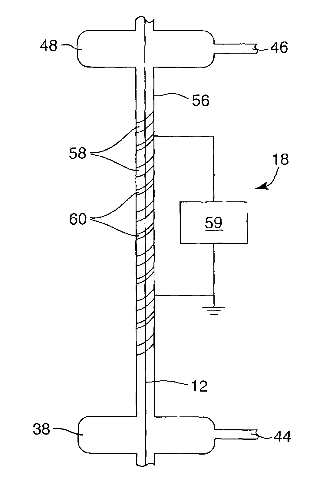
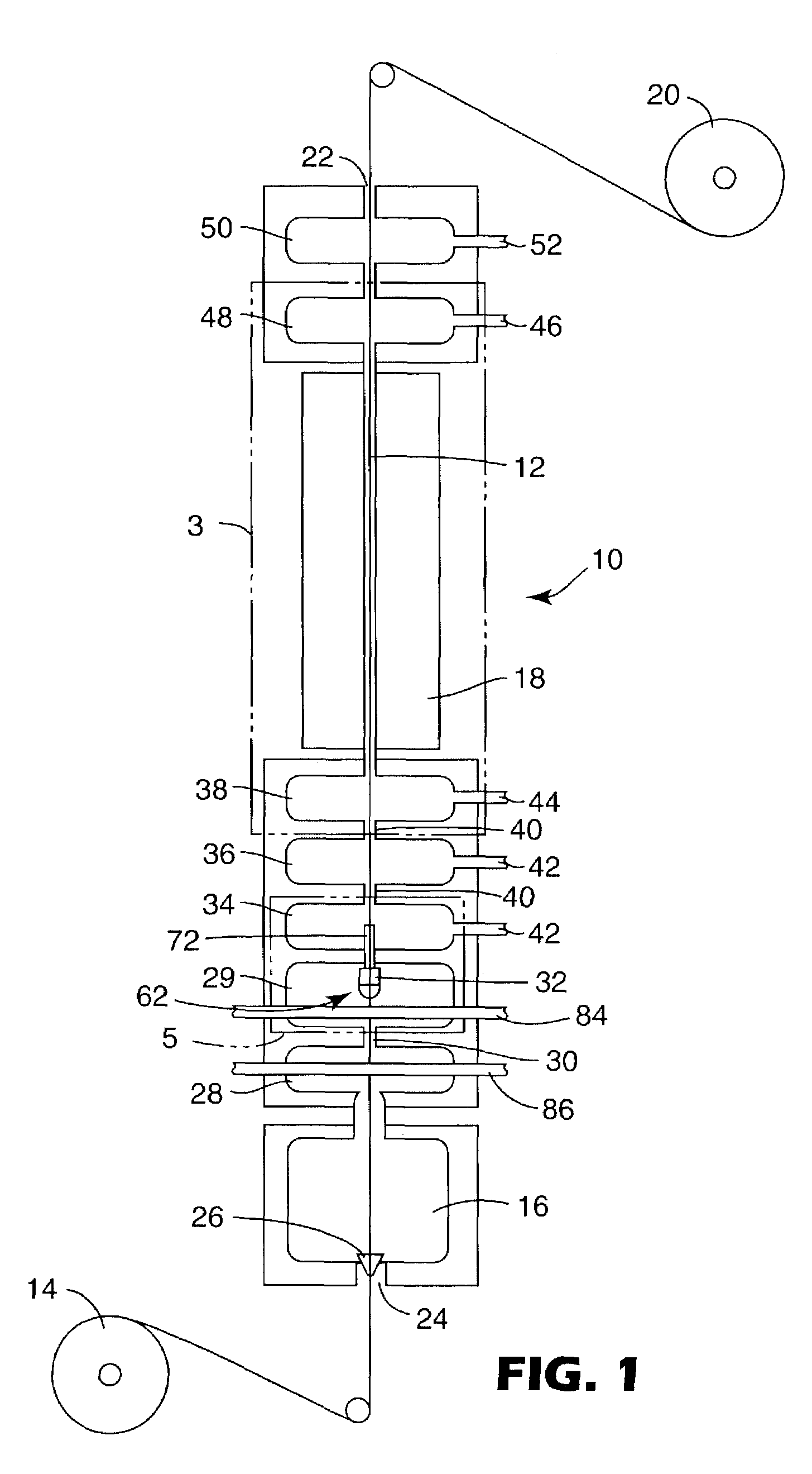
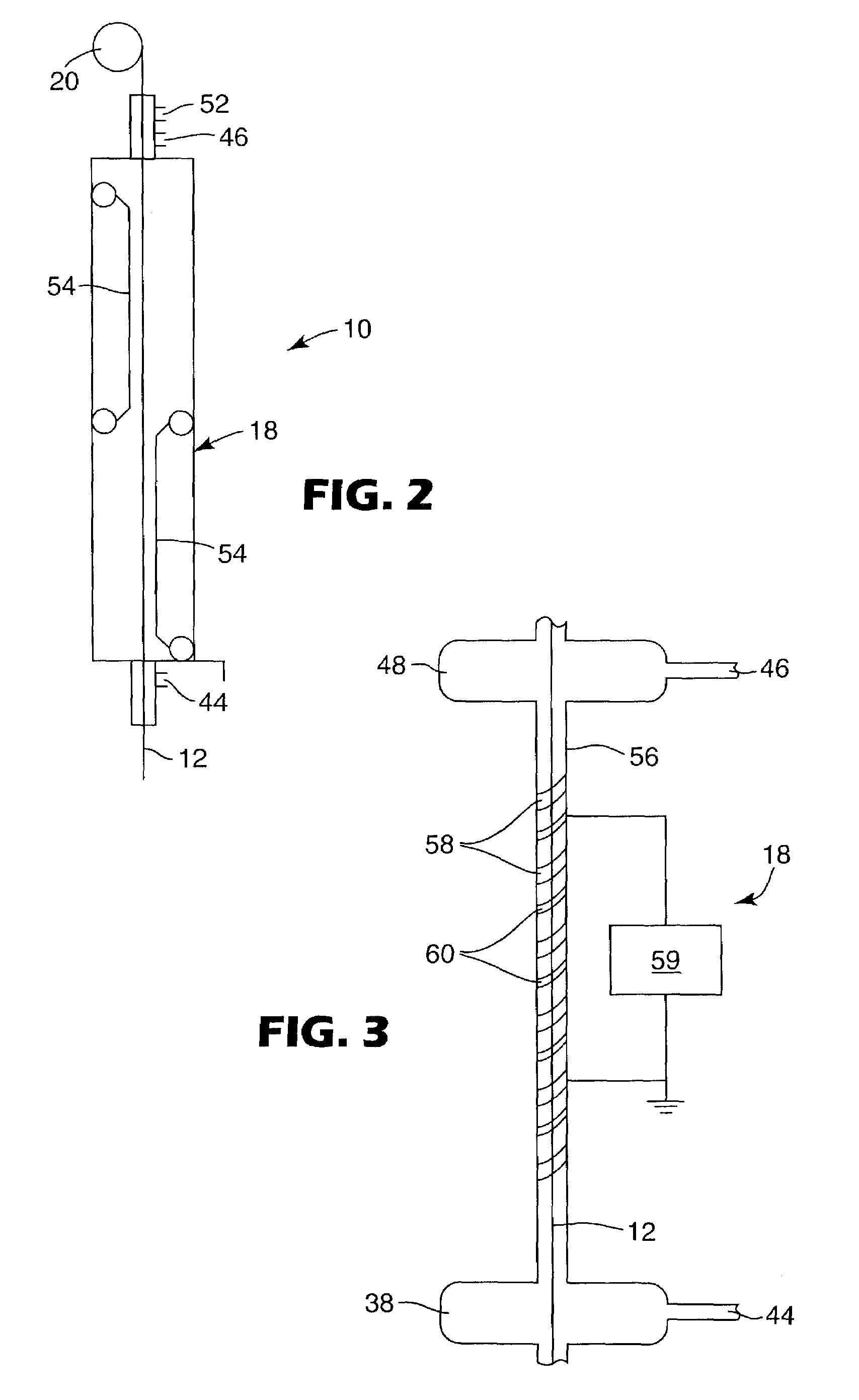
[0063]A tubular reaction chamber was constructed using a PYREX® glass tube, 122 cms (four feet) long, having an internal diameter of approximately 1.00 cm (0.4 inch). A pair of electrodes was wrapped helically around the outside of the glass tube for a length of approximately 91.5 cm (three feet) to provide the tubular structure shown in FIG. 3. The electrode-wrapped tube provided the low-pressure plasma reactor used to deposit diamond-like glass coatings on stripped optical fibers threaded through the optical fiber processing equipment shown in FIG. 1.

[0064]The use of two electrodes, wrapped as a double helix around the outside of the tubular reaction chamber, provides a localized electric f...


PUM

PropertyMeasurementUnit
Radiusaaaaaaaaaa
Radiusaaaaaaaaaa
Lengthaaaaaaaaaa

Abstract

A device for forming an ion sheath in a plasma to deposit coatings on a non-conducting substrate. The device comprises a tubular reaction chamber having an outer surface wound helically with a first electrode having a first width. Helical winding of the first electrode provides a plurality of first wraps around the outer surface of the tubular reaction chamber. The device further includes a second electrode having a second width that is larger than the first width. Helical winding of the second electrode provides a plurality of second wraps alternating with the first wraps around the outer surface of the tubular reaction chamber. An ion sheath in a plasma forms to a thickness extending at least to the longitudinal axis of the tubular reaction chamber when the first electrode has a connection to a source of radio-frequency power and the second electrode provides a path to ground.

Description

BACKGROUND OF THE INVENTION[0001]1. Field of the Invention[0002]The invention relates generally to coated optical fibers and to a device and method for contacting and positioning lengths of uncoated optical fiber for application, by chemical vapor deposition, of amorphous or metal coatings without adverse effect upon the strength characteristics of the uncoated optical fibers. More particularly the present invention provides a coating apparatus including a plasma reactor in the form of a tubular reaction chamber having powered and grounded electrodes wound helically on the outer surface of the tubular reaction chamber. The present invention further provides a fiber guide formed by freezing a layer of liquid, preferably water, to provide a solid collar that acts as a bearing for linear movement of a fiber along a prescribed axis during application of amorphous material, including diamond-like glass coatings, inside low pressure reaction chambers.[0003]2. Description of the Related Ar...

Claims


Application Information

Patent Timeline
IPC IPC(8): C23C16/00H01L21/306C23C16/509C23C16/54H01J37/32
CPCC23C16/507C23C16/545H01J37/321H01J37/3277H01J37/32541H01J37/32568
Inventor DAVID, MOSES M.GIFFORD, MICHAEL C.
Owner 3M INNOVATIVE PROPERTIES CO
Why Eureka
Try Eureka