
Phosphor and manufacturing method for the same, and light emitting device using the phosphor

a technology of phosphor and manufacturing method, which is applied in the direction of discharge tube/lamp details, luminescent compositions, discharge tubes/lamp details, etc., can solve the problems of short life span, poor emission efficiency, and phosphor thus containing, and achieve excellent durability against heat and water, and improved emission intensity and luminance.

Inactive Publication Date: 2009-01-13
DOWA ELECTRONICS MATERIALS CO LTD
View PDF88 Cites 3 Cited by
  • Summary
  • Abstract
  • Description
  • Claims
  • Application Information

AI Technical Summary

Benefits of technology

The present invention provides a new phosphor with excellent emission efficiency and luminance under excitation of an excitation light of near ultraviolet to green color. The phosphor has a wide excitation band in a broad region from the near ultraviolet to green color and a strong emission intensity. The manufacturing method of the phosphor is simple and uses a raw material structure that can be easily mixed even in atmospheric air. The phosphor can be used in a white light emitting device and has a high relative intensity of the maximum peak in the emission spectrum. The composition of the phosphor is given by a specific formula and contains specific elements in a specific ratio to achieve the desired properties.

Problems solved by technology

At present, a discharge type fluorescent lamp and an incandescent bulb used as the illumination device involve problems that a harmful substance such as mercury is contained, and life span is short.
However, the phosphor thus containing nitrogen according to the conventional art does not have an emission efficiency with satisfactory level under an excitation of an excitation light from the near ultraviolet / ultraviolet to green regions, thereby not having a sufficient emission intensity and luminance.
Therefore, although the white LED lighting unit having the excellent durability can be manufactured, the luminance, which is an important element, becomes insufficient when the light emitting device is manufactured by combining the near ultraviolet / ultraviolet LED, blue LED, etc., and the phosphor thus containing nitrogen, because the emission intensity and the luminance are insufficient.
Further, as a manufacturing method of the phosphor thus containing nitrogen according to the conventional art, there is no choice but use a nitride raw material which is unstable in an atmospheric air, because the emission efficiency is decreased when a slight amount of oxygen is included during mixing the raw materials.
Also, there is no choice but use the method of treating and mixing the raw materials in the inert atmosphere to prevent the oxidization of the nitride raw material during mixing the raw materials, or fire the raw materials in a strong reducing atmosphere and a nitride atmosphere such as 100% ammonia.
Therefore, it is difficult to improve the productivity.

Method used


Image

  • Phosphor and manufacturing method for the same, and light emitting device using the phosphor
  • Phosphor and manufacturing method for the same, and light emitting device using the phosphor
  • Phosphor and manufacturing method for the same, and light emitting device using the phosphor

Examples


example 1

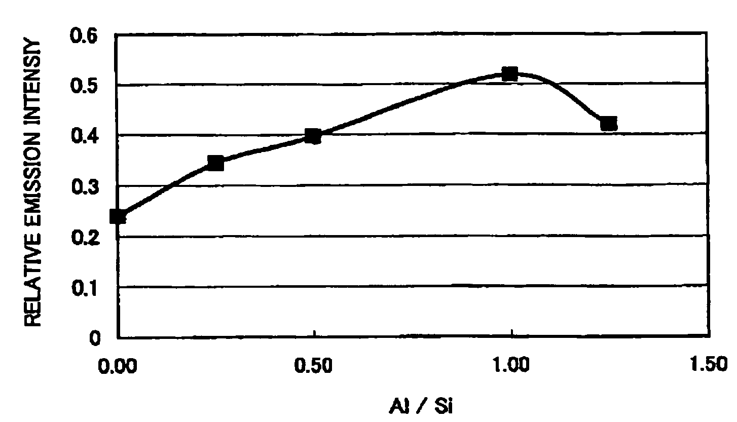
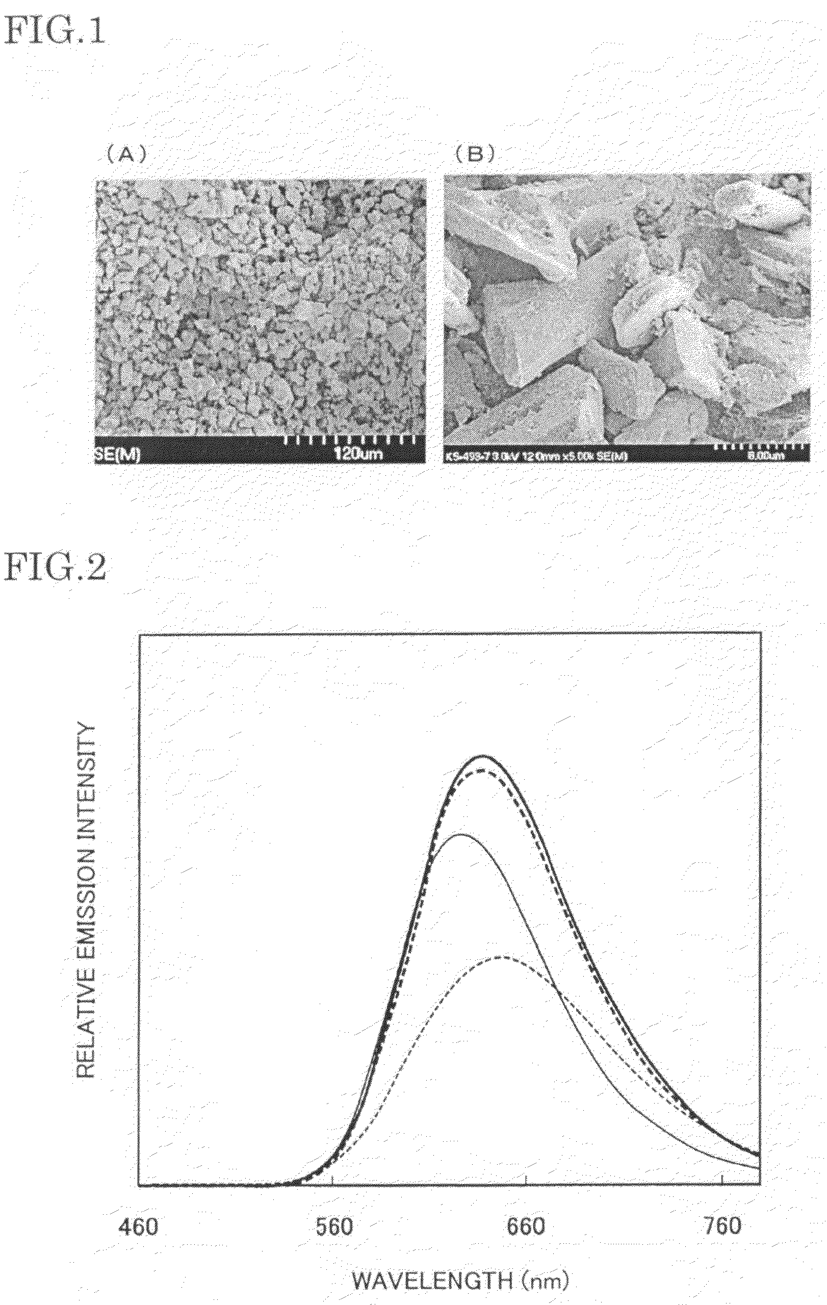
[0097]Commercially available SrCO3 (3N), AlN (3N), Si3N4 (3N) were prepared as each raw material of the element M, the element A, and the element B, and Eu2O3 (3N) was prepared as the element Z, so that the molar ratio of each element becomes Sr:Al:Si:Eu=0.970:0.25:2.75:0.030. Then, each raw material was weighed to obtain 0.970 mol of SrCO3, 0.25 mol of AlN, 2.75 / 3 mol of Si3N4, and 0.030 / 2 mol of Eu2O3, and the raw materials thus weighed were mixed by using the mortar in the atmospheric air. The raw materials thus mixed were put in a BN crucible, then the temperature was increased up to 1800° C. at 15° C. / min under the furnace pressure of 0.05 MPa in a nitrogen atmosphere (in a flow state), and retained / fired for 3 hours at 1800° C. Thereafter, the raw materials thus fired were cooled from 1800° C. to 200° C. for 1 hour, then a fired sample was pulverized up to a proper particle size in the atmospheric air by using the mortar, to obtain the phosphor according to an embodiment 1 exp...

example 2

[0108]In the example 2, the phosphor of the example 2 is manufactured in the same way as the example 1, other than the molar ratio of each element of the example 1 which is set to Sr:Al:Si:Eu=0.970:0.25:2.5:0.030.

[0109]Commercially available SrCO3 (3N), AlN (3N), Si3N4 (3N), and Eu2O3 (3N) were prepared, so that the molar ratio of each element becomes Sr:Al:Si:Eu=0.970:0.25:2.5:0.030. Then, each raw material was weighed to obtain 0.970 mol of SrCO3, 0.25 mol of AlN, 2.5 / 3 mol of Si3N4, and 0.030 / 2 mol of Eu2O3, and the raw materials thus weighed were mixed by using the mortar in the atmospheric air. The raw materials thus mixed were put in the BN crucible, then the temperature was increased up to 1800° C. at 15° C. / min under the furnace pressure of 0.05 MPa, and retained / fired for 3 hours at 1800° C. in the nitrogen atmosphere (in a flow state). Thereafter, the raw materials thus fired were cooled from 1800° C. to 200° C. for 1 hour, then a fired sample was pulverized up to a proper...

example 3

[0114]In the example 3, in the phosphor expressed by the composition formula Sr4AlSi11O2N17:Eu of the phosphor of the example 1, Eu was replaced with Ce as the activator. Otherwise, in the same way as the example 1, the phosphor of the example 3 Sr4AlSi11O2N17:Ce was manufactured in the same way as the example 1. The molar ratio of each element is Sr:Al:Si:Ce=0.970:0.25:2.75:0.030, and each raw material was weighed to obtain 0.970 mol of SrCO3, 0.25 mol of AlN, 2.75 / 3 mol of Si3N4, and 0.030 mol of CeO2. The composition estimated from the raw material used and the blending ratio was given by Sr4AlSi11O2N17:Ce (wherein Ce / (Sr+Ce)=0.030). In the same way as the example 1, the analysis result of the phosphor powder thus obtained is shown in table 1.

[0115]A composition analysis result of the phosphor thus obtained was estimated from the amount of atoms and the molar ratio of the constituent element in the same way as the example 1. The result was close to the composition ratio of Sr4AlS...


PUM

PropertyMeasurementUnit
wavelengthaaaaaaaaaa
peak wavelengthaaaaaaaaaa

Abstract

To provide a phosphor having an emission spectrum with a broad peak in range from green color to red color, and having excellent emission efficiency and luminance. A phosphor is provided, which is given by a general composition formula expressed by MmAaBbOoNn:Z, (where element M is more than one kind of element having bivalent valency, element A is more than one kind of element having tervalent valency, element B is more than one kind of element having tetravalent valency, O is oxygen, N is nitrogen, and element Z is more than one kind of element acting as an activator.), satisfying 2.5<(a+b) / m<4.5, 0<a / m<2.0, 2.0<b / m<4.0, 0<o / m<1.0, o<n, n=2 / 3m+a+4 / 3b−2 / 3o.

Description

TECHNICAL FIELD OF THE INVENTION[0001]The present invention relates to a phosphor containing nitrogen used in a display such as a cathode-ray tube (CRT), a field emission display (FED), and a plasma display (PDP), a semiconductor light emitting device (referred to as LED in some cases hereafter), and an illumination device such as a fluorescent lamp and a fluorescent display tube, and a light emitting appliance such as a back light for liquid crystal display, and a method of manufacturing of the same, and also to a light emitting device such as a white LED lighting unit in which the LED and the phosphor are combined.BACKGROUND OF THE INVENTION[0002]At present, a discharge type fluorescent lamp and an incandescent bulb used as the illumination device involve problems that a harmful substance such as mercury is contained, and life span is short. However, in recent years, a high luminescence LED emitting light of blue to near ultraviolet / ultraviolet region has been developed in sequenc...

Claims


Application Information

Patent Timeline
Patent Type & Authority Patents(United States)
IPC IPC(8): C09K11/59C09K11/64H01L33/50
CPCC09K11/0883C09K11/7715C09K11/7721C09K11/7728C09K11/7734H05B33/14C09K11/77218C09K11/77348
Inventor NAGATOMI, AKIRAIKUTA, TETSUYAYAMASHITA, SHUJI
Owner DOWA ELECTRONICS MATERIALS CO LTD
Learn More