Instrument for surgically cutting tissue and method of use

a tissue and surgical technology, applied in the field of instruments and methods for surgical cutting of tissue, can solve the problems of difficult for such instruments to harvest tissue from patients difficult for such instruments to achieve tissue extraction under realistic clinical conditions, and lack of tissue plane separation capability at site prior to tissue removal, etc., to facilitate diagnosis of possible abnormal tissue, facilitate accurate apposition of edges, and promote primary healing

Inactive Publication Date: 2009-01-27
LSI SOLUTIONS
View PDF38 Cites 94 Cited by
  • Summary
  • Abstract
  • Description
  • Claims
  • Application Information

AI Technical Summary

Benefits of technology

[0008]It is another object of the present invention to provide an instrument for surgically cutting tissue which enables large tissue biopsies to be taken at a certain depth to facilitate diagnosis of possible abnormal tissue.
[0009]A further object of the present invention is to provide an instrument for surgically cutting tissue in which the shape of the cut in the tissue facilitates accurate apposition of the edges of the tissue for wound closure which promotes primary healing.
[0015]The tissue so removed by the instrument may represent a tissue specimen for biopsy for subsequent diagnostic evaluation (e.g., histologic review). If the entire pathologic element of the tissue sample is completely removed by one or repeated use of the instrument, the process may be considered therapeutic and no further patient interaction may be required. When appropriate, resulting wound edges at the site of the removed tissue can be apposed to further augment healing of the wound closure.
[0019]Thus, the instrument of the present invention provides precision removal of tissue of a predetermined depth and volume (length, width, and height). A mechanical means securely gain purchase on targeted tissue and appropriately hold it throughout the removal process, such as is provided herein with the vacuum (suction), needle and blade combination, enables effective tissue capture and retrieval at more remote locations within the body and without requiring direct manual manipulation by a health care provider, such as a surgeon. The use of needles for the remote injection of mixtures of sterile fluids, not only provides for a convenient and reliable way of delivering soluble pharmaceutical agents (such as epinephrine, a hemostatic agent, to control blood loss, and lidocaine, a local anesthetic, to minimize related discomfort), it also provides for accurate bulk fluid delivery (e.g., a normal saline carrier) to enable mechanical tissue plane separations using pressurized fluid volume injections. Further, the instrument is useful for removing tissue from specified locations in tubular structures, such as in the gastrointestinal or urinary tract, or vascular structures of a patient, or in any other tissue surface or soft tissue in a patient's body which is naturally or surgically accessible. Also, the instrument enables large specimen harvest and more complete removal of intact tissue specimens which can provide therapeutic relief. The instrument and method addresses a persistent problem by enabling precision tissue removal with minimizing patient morbidity while maximizing the health care provider's effectiveness.

Problems solved by technology

While instruments have been designed with simple blades and rotors for cutting or chopping tissue, they do not provide precision removal of a tissue specimen of a predetermined length, width and depth.
It is also difficult for such instruments to harvest tissue from a patient under realistic clinical conditions and to safely access remote locations in the patient.
Further, such instruments lack the capability to effect separation of tissue planes at a site prior to tissue removal, or to deliver therapeutic agents to tissue.
Although such devices may be useful for their particular limited applications, they do not generally control for precise tissue sample size or cutting depth, mechanical tissue engagement, preservation of biopsy specimen for subsequent examination, or injectable fluid delivery.
Accurate forceps placement remains problematic as does frequent bleeding at the biopsy site, further obscuring accurate tissue harvest.
The physical location of such tissue in the esophagus makes alternative non-invasive medical intervention along the gastrointestinal tract difficult.
However, this approach may be limited to capturing nodular areas, rather than a long segment of the esophageal lining.
Like other surgical cutting instruments described earlier, it is difficult using these approaches to remove tissue to precisely control the cutting depth into the esophageal lining, which can result in inadequate removal of mucous membrane or inadvertent removal of sub-mucosal layers leading to possible esophageal wall perforation.
Further in the case of U.S. Published Patent Application No. 2001 / 0049509, the use of forceps and knifes represents a manual time consuming process prone to human error.
A further problem of these approaches is that if the wound in the esophageal lining is to be closed, such as by suturing (i.e., stitches) or other closure devices, there may not be proper tissue edges on either side of the wound to appose, resulting in failure of stitches or tearing of stitches through the tissue, and may lead to failure of primary healing.

Method used


Image

  • Instrument for surgically cutting tissue and method of use
  • Instrument for surgically cutting tissue and method of use
  • Instrument for surgically cutting tissue and method of use

Examples


Embodiment Construction

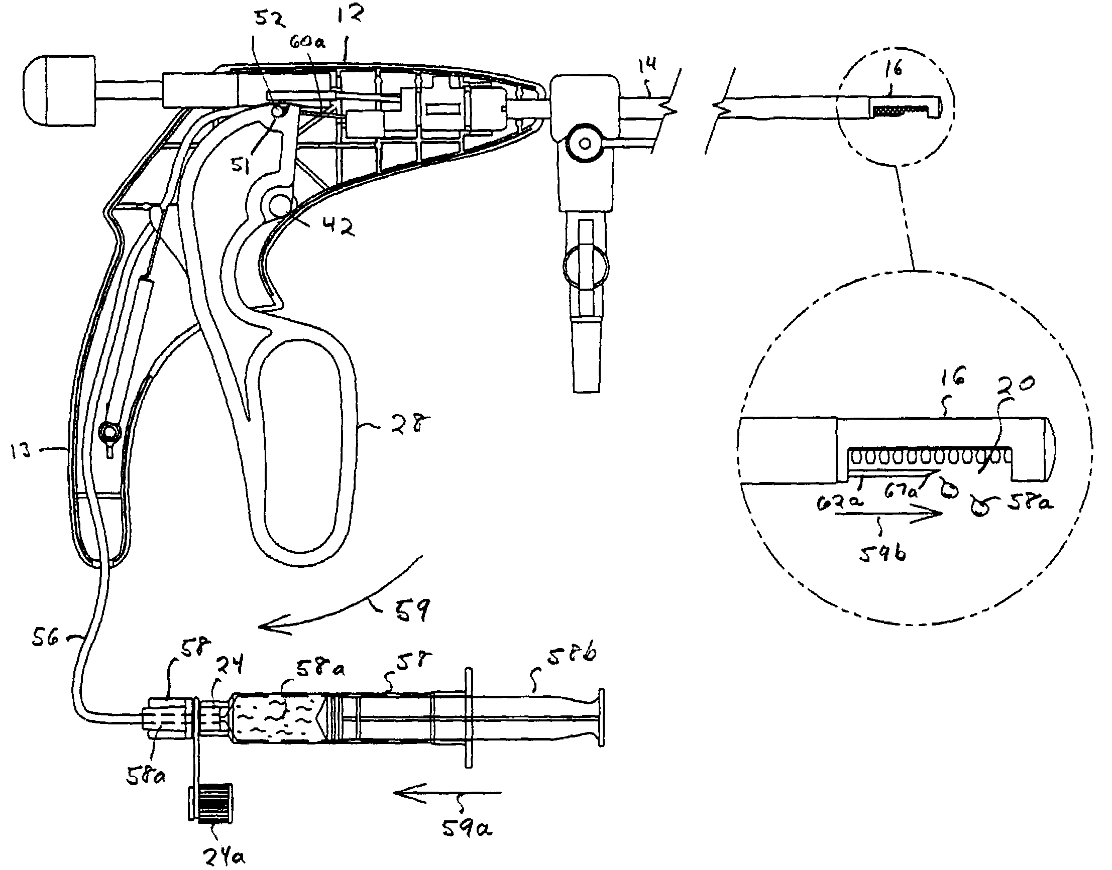
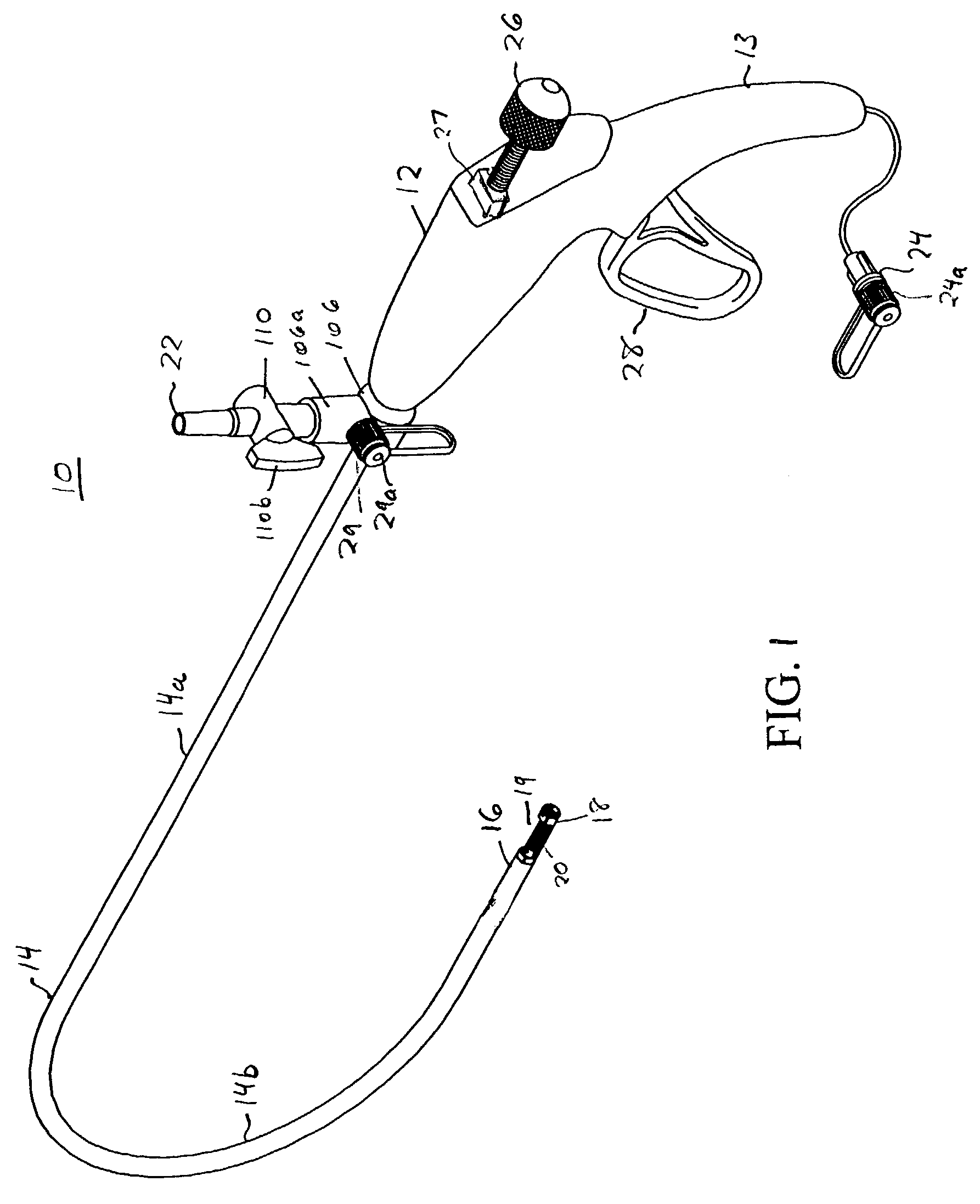
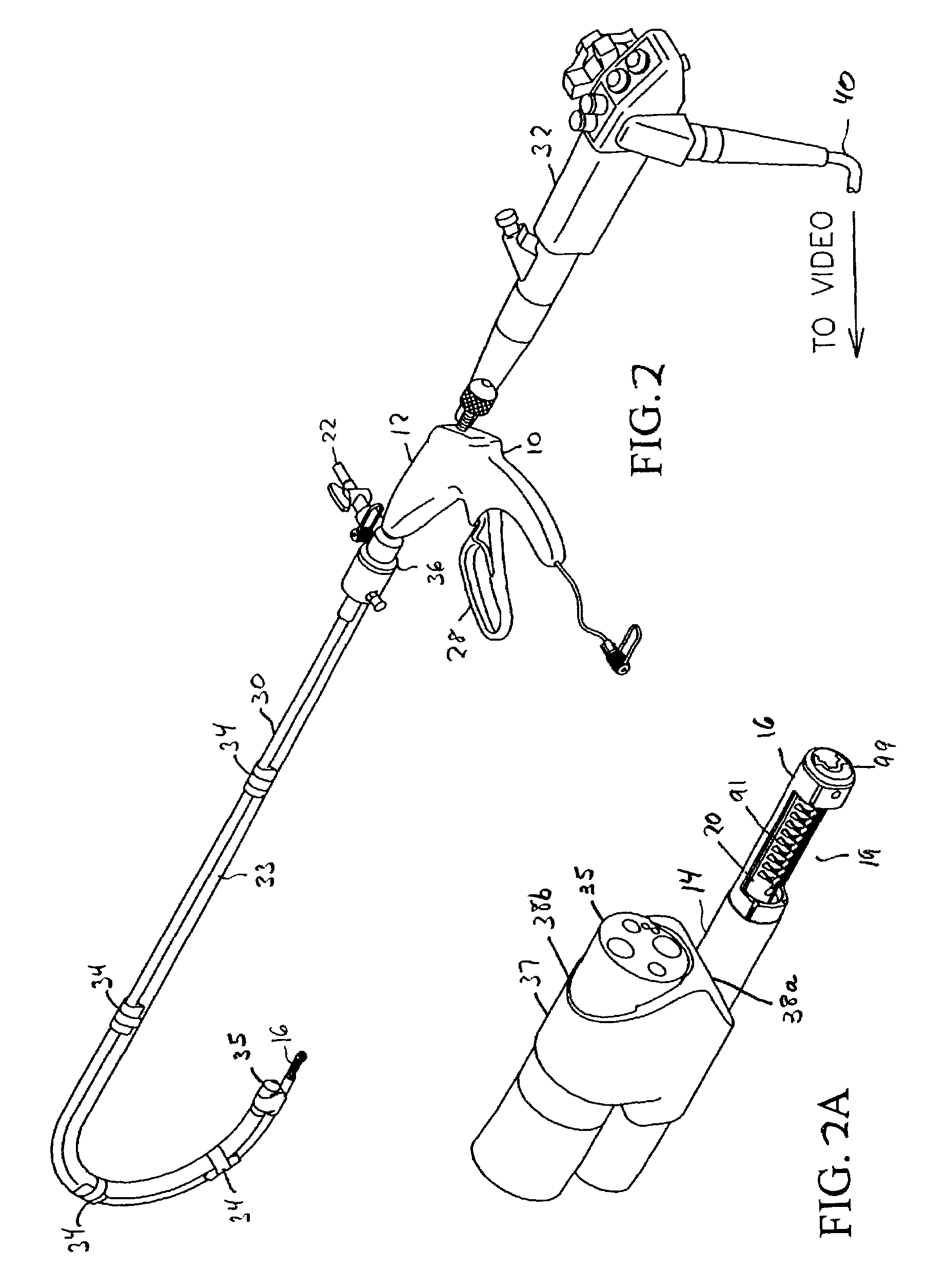
[0072]Referring to FIG. 1, the instrument 10 of the present invention is shown having a housing 12 and a shaft 14 extending from the housing 12 to a distal end 16. The shaft 14 has a first rigid section 14a and then a second flexible section 14b to facilitate location of the distal end 16 along the curvature of a tubular structure, such as along the gastrointestinal tract, urinary tract, or vascular structures of a patient's body. The shaft 14 is of a cylindrical cross-sectional shape with an outer diameter enabling the shaft to be inserted in a tubular structure to locate the distal end 16 in such tubular structure of a patient. The housing 12 has a body shaped like a pistol having a handle portion 13, and may be made of a two-piece construction of molded plastic. At the distal end 16 of the shaft 14 is a distal housing 18 with an opening 19 to a cavity 20. The instrument 10 has a vacuum port 22 along shaft 14 for applying suction to the distal end 16, a turn screw 26 for controlli...


PUM


Abstract

An instrument for precisely cutting tissue to controlled dimensions (length, width, depth, and shape) is provided for the removal of tissue specimens from remote sites in the body of a patient, such as from the gastrointestinal tract, urinary tract, or vascular structures, or any tissue surface or soft tissue of the body. The instrument has a housing and a substantially flexible shaft extending from the housing to a distal end. The distal end of the instrument has an open cavity into which tissue is receivable. Suction can be communicated along the shaft to the distal end for distribution across the cavity utilizing a manifold having a grated tissue engaging surface with opening(s) for applying the suction, thereby pulling tissue adjacent to the distal end into the cavity against the tissue engaging surface of the manifold. One or more hollow needles are extendable from the housing through the shaft into the cavity to enable infusion of fluid, such as saline or a hemostatic agent, into the tissue. A blade in the distal end is extendable through the cavity over the manifold and across the opening to cut the tissue held by suction and stabilized by the needles in the cavity. The shape and depth of the tissue removed by the cuts is in accordance with the contour of the tissue engaging surface and the size and shape of the cavity at the distal end. The tissue so removed by the instrument may be for therapeutic intervention and / or represent a tissue specimen for biopsy suitable of diagnostic evaluation. The tissue edges in the patient's body left after cutting with this instrument readily avail themselves to apposition for enhanced healing.

Description

FIELD OF THE INVENTION[0001]The present invention relates to an instrument (and method) for surgical cutting of tissue in the body of a patient, and in particular, to remote surgical cutting of tissue in the body of a patient to a precise length, width, and depth, and overall shape. The invention is useful for surgical removal of tissue from a site in the body of a patient, including, the lining of tubular structures, such as the gastrointestinal tract (e.g., the esophagus or stomach), urinary tract, or vascular structures, but may also be used to remove tissue from any tissue surface (e.g., surface of the liver, lining of the peritoneal cavity), or within soft tissue structures (e.g., from within breast or brain tissue).BACKGROUND OF THE INVENTION[0002]A need exists for an improved surgical instrument to enable safe and efficacious removal of living tissue during diagnostic and therapeutic medical interventions. While instruments have been designed with simple blades and rotors for...

Claims


Application Information

Patent Timeline
Patent Type & Authority Patents(United States)
IPC IPC(8): A61B17/32A61B10/00A61B10/02A61B10/04A61B17/22A61B17/30
CPCA61B10/04A61B10/0283A61B17/320016A61B17/320783A61B2010/0225A61B2017/00269A61B2017/306A61B2017/320064
Inventor SAUER, JUDE S.
Owner LSI SOLUTIONS
Why Eureka
Try Eureka