Rapid serial experimentation of catalysts and catalyst systems

a catalyst and serial experiment technology, applied in the field of catalyst testing, can solve the problems of unreliable methodology, low efficiency of de19809477c2, and slow step in the sequence characterization of catalysts, and achieve the effects of short reaction time, improved efficiency, and faster cycle of reactors

Inactive Publication Date: 2009-01-27
EXXON RES & ENG CO
View PDF17 Cites 3 Cited by
  • Summary
  • Abstract
  • Description
  • Claims
  • Application Information

AI Technical Summary

Benefits of technology

[0008]It has been discovered that serial testing of catalysts and catalyst systems may be made advantageously more efficient through the use of a multi-station testing arrangement and automating the testing protocol to enable faster cycling of reactors (or short reaction times) resulting in a decrease in the cumulative time to test, characterize, and change reactors.

Problems solved by technology

As a whole, the sequential characterization of catalysts becomes the slow step and is no longer high-throughput.
DE19809477C2 is not always effective in evaluating materials in which reaction testing and characterization techniques must be combined to present a complete analysis.
However, this methodology is unreliable because it requires that all species be measured and be measured accurately.
Missing components and propagation of error lead to highly inaccurate, scattered results.
Thus, calculating coke from all of those measurements is rendered unusable.
The direct measurement of coke (likely via combustion) is not a viable solution for parallel reactor systems because the arrays of materials may have to be unloaded from the reactor into a new reactor for de-coking and tested one-by-one.
Another approach is to redesign the hydrocarbon feed system to include both air and hydrocarbon feeds that are appropriately separated by interlocks (although possible, also of considerable hazard) to accomplish the coke measurement.
All of these approaches become a bottleneck to high-throughput experimentation.
Compromise must be reached between data quality and complexity.
As a result, parallel apparatus do not contain sufficient instrumentation to control key process parameters i.e. pressure, flow, and temperature for each individual reactor.
In addition, some parameters have a limited range of operation temperature for “massively parallel.” While catalyst performance can be tested for many catalysts at once, data quality suffers.
This leads to high variability in measured results.

Method used


Image

  • Rapid serial experimentation of catalysts and catalyst systems
  • Rapid serial experimentation of catalysts and catalyst systems
  • Rapid serial experimentation of catalysts and catalyst systems

Examples


example 1

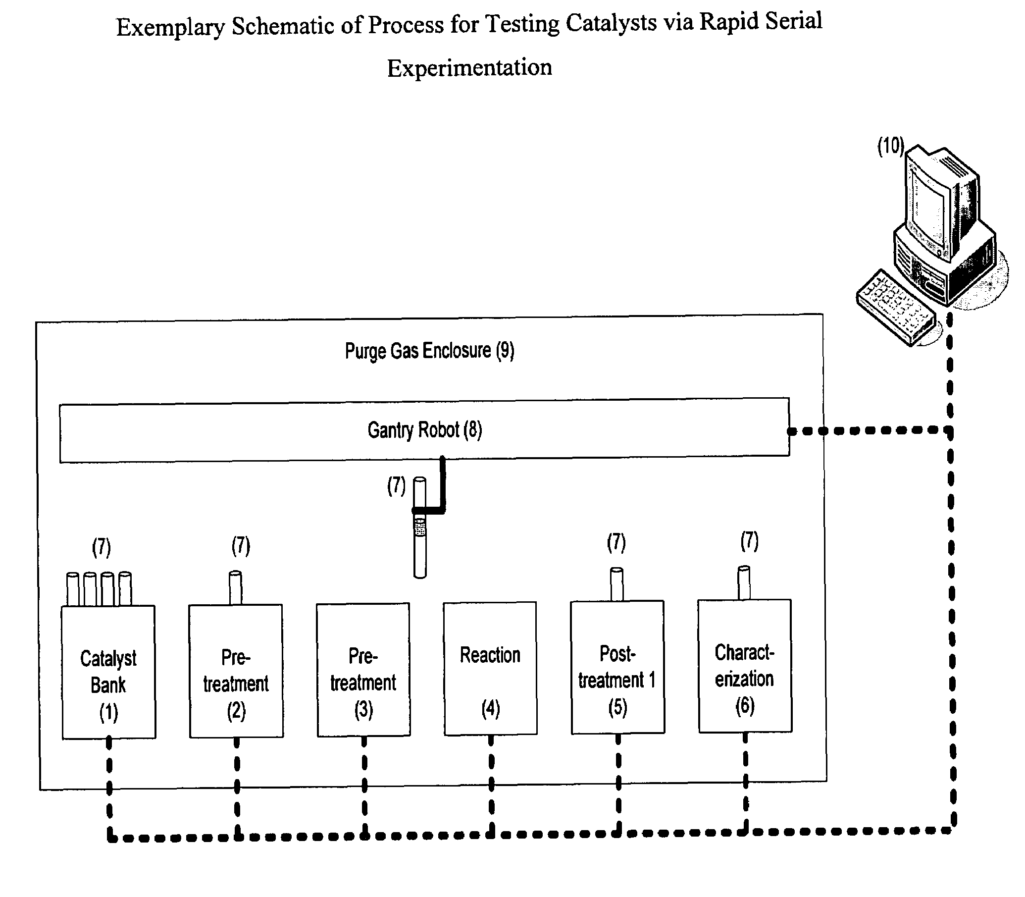
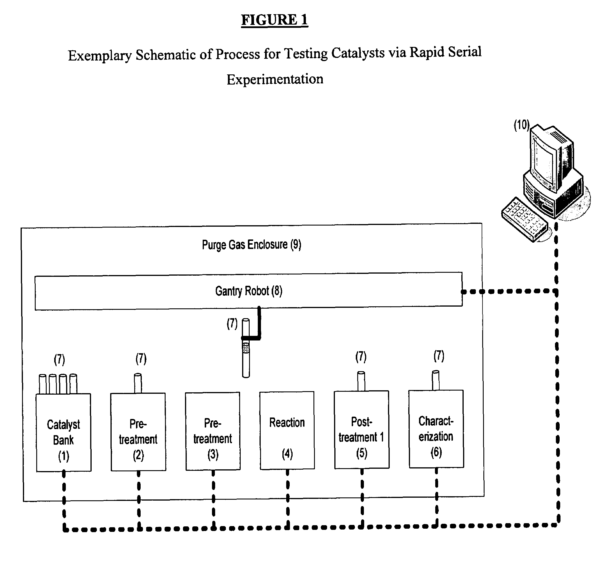
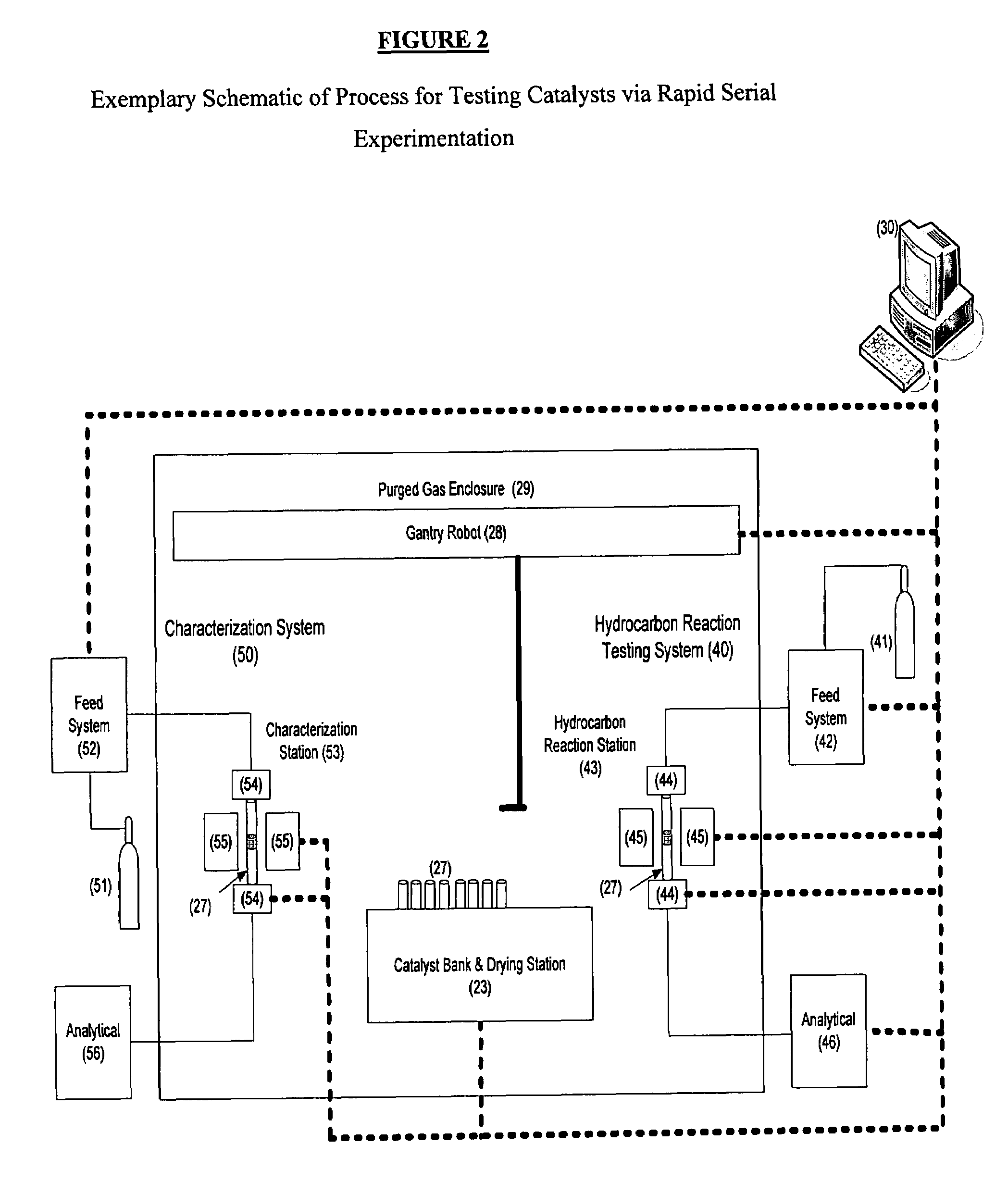
[0054]A storage station or tray of pre-calcined catalyst packed tubular reactors (0.25 g each) was placed in the ante-chamber of a glove box. The ante-chamber was evacuated then nitrogen purged to 4 inches of water (gauge). The tray was then transferred to a heating block within the inert atmosphere of the glove box. The heating block already contained several trays currently in use for reaction testing and de-coking. Twenty-five catalyst packed reactors, situated in the trays in the heating block, had come to a steady-state temperature of 120° C. Each reactor within the heated tray were also continuously exposed to an inert purge to dry each catalyst for sufficient time so that each catalyst packed reactor was considered appropriately pre-treated and available for hydrocarbon testing. Automated robots selected a reactor tube from the pre-loaded tray and transferred it into the hydrocarbon assembly for testing. A furnace at 400° C., consisting of two sides, was then actuated (roboti...

example 2

Comparative

[0057]A reactor is packed with 0.25 g of catalyst. The reactor was manually loaded into a conventional 3 zone furnace assembly (required about 0.5 hr). It was pressure tested and then heated from 30° C. to 120° C. at 1° C. / min and held for 1 hour to enable drying (total time of 2.5 hours). The catalyst packed reactor was then heated to 800° C. at 5° C. / min. Hydrocarbon gas was then fed and allowed to react for approximately 1 hour. Total time for reaction was approximately 3.3 hours. Because of the mass of the traditional furnace and without fans, cool down required about 2 hours. At the same time, a sample of spent catalyst (different) was loaded on to a set-up to complete temperature programmed oxidation from 25° C. at 5° C. / min to 800° C. Because the reactor had to be unloaded, and a TGA (Thermogravametric Analysis Instrument) pan loaded, 0.5 hrs was required to load the instrument. In addition, without an inert atmosphere, the oxidation had to be begun at 25° C. inste...

example 3

[0060]The method of example 1 whereby the process flow was controlled via differential pressure across a critical orifice or by use of an automated variable orifice, such as a valve.


PUM

PropertyMeasurementUnit
steady-state temperatureaaaaaaaaaa
timeaaaaaaaaaa
timeaaaaaaaaaa

Abstract

The present invention relates to a method of testing catalysts and catalyst systems via a plurality of stations in which each station can accommodate a common reactor module in order to accomplish unattended, automated, rapid serial experimentation. The method includes the steps of: providing within a purged chamber a storage station of pre-loaded catalyst reactors, a hydrocarbon reaction station, one or more additional pre-treatment and / or post-treatment stations in series with said hydrocarbon reaction station, and a robotic means for moving catalyst reactors within the purged chamber between stations, pre-treating the pre-loaded catalyst reactor with a treatment gas in the post-treatment station, reacting the pre-loaded catalyst reactor with a hydrocarbon reactant in the hydrocarbon reaction station, post-treating the pre-loaded catalyst reactor with a treatment gas in the post-treatment station, and repeating the foregoing steps such that the pre-treating, reacting and post-treating steps occur simultaneously for two different pre-loaded catalyst reactors. The advantages of the present invention include improved accuracy, reproducibility and quality of test data generated, increased testing throughput rate, providing for automated unattended operation of the device, providing for the ability the ability to program a variety of sequences and settings, providing for the combination of a variety of processes (pre-treatment, HC reaction testing, post-treatment, aging, and characterization), and providing for higher temperature operation. The method finds application in laboratory test environments, and in particular in high throughput testing environments.

Description

CROSS-REFERENCE TO RELATED APPLICATION[0001]This application claims the benefit of U.S. Provisional Application 60 / 830,913 filed Jul. 14, 2006.FIELD OF THE INVENTION[0002]The present invention relates to the field of catalyst testing. It more particularly relates to an improved method of testing catalysts and catalyst systems through automation. Still more particularly, the present invention relates to an improved method of testing catalysts and catalyst systems by incorporating both catalyst treatment and reaction testing and characterization into distinct stations for simultaneous experiments.BACKGROUND OF INVENTION[0003]High throughput catalyst testing has been often accomplished via the “massively parallel” approach discussed in High-Throughput Screening in Chemical Catalysis (2004 Wiley-VCH Verlag GmbH & Co. and KGaA, Weinheim. In this prior art, an array of materials are tested as a single batch in a manner that is highly dependent on manual operation. In this experimentation ...

Claims


Application Information

Patent Timeline
Patent Type & Authority Patents(United States)
IPC IPC(8): G01N31/10B01J8/00
CPCG01N31/10Y10T436/11Y10T436/25875
Inventor VINCENT, MATTHEW J.IACCINO, LARRY L.PIERCE, JOHN K.KING, DOUGLAS B.COX, TOBY W.
Owner EXXON RES & ENG CO
Why Eureka
Try Eureka