Modified delivery device for coated medical devices

a medical device and coating technology, applied in the field of local administration of drug/drug combinations, can solve the problems of ischemic injury, stroke, or myocardial infarction, angioplasty is the abrupt closure of the vessel, and chronic pain, so as to reduce the frictional force acting on specific areas, reduce the potential risk of damage, and reduce the effect of frictional for

Inactive Publication Date: 2009-05-05
CARDINAL HEALTH SWITZERLAND 515 GMBH
View PDF35 Cites 838 Cited by
  • Summary
  • Abstract
  • Description
  • Claims
  • Application Information

AI Technical Summary

Benefits of technology

[0029]In order to be effective, the drugs, agents or compounds should preferably remain on the medical devices during delivery and implantation. Accordingly, various coating techniques for creating strong bonds between the drugs, agents or compounds may be utilized. In addition, various materials may be utilized as surface modifications to prevent the drugs, agents or compounds from coming off prematurely.
[0030]Alternately, the delivery devices for the coated implantable medical device may be modified to minimize the potential risk of damage to the coating or the device itself. For example, various modifications to stent delivery devices may be made in order to reduce the frictional forces associated with deploying self-expanding stents. Specifically, the delivery devices may be coated with various substances or incorporate features for reducing the forces acting upon specific areas of the coated stent.
[0031]The self-expanding stent delivery system of the present invention comprises a sheath coated with a layer of pyrolytic carbon or similar substance. The layer of pyrolytic carbon may be affixed to the inner lumen of the sheath in the region of the stent or along the entire length of the sheath. The pyrolytic carbon is hard enough to prevent the self-expanding stent from becoming embedded in the softer polymeric sheath. In addition, pyrolytic carbon is a lubricious material. These two properties reduce the change of damage to the stent during deployment, reduce the forces required for stent deployment, thereby making it easier for the physician to accomplish placement, and provide for more accurate stent deployment.
[0032]The pyrolytic carbon may be directly affixed to the inner lumen of the sheath or to a substrate which is then affixed to the inner lumen of the sheath. A variety of known techniques may be utilized in the manufacturing process. Pyrolytic carbon is biocompatible and is currently utilized in a number of implantable medical devices. The pyrolytic carbon layer is sufficiently thick to provide the above-described features and thin enough to maintain the overall profile and flexibility of the delivery system.
[0033]The lubricious nature of the pyrolytic carbon is particularly advantageous with drug coated stents. The drug coatings and polymer containing drugs, agents or compounds should preferably remain on the stent for best results. A lubricious coating on the sheath substantially reduces the risk of the drug or polymer from rubbing off during delivery.
[0034]The self-expanding stent delivery system of the present invention may also comprise a modified shaft. The modified shaft may include a plurality of elements which protrude from the shaft in the gaps between the stent elements. These elements may significantly reduce the forces acting upon the stent during deployment by preventing or substantially reducing the compression of the stent. Without the plurality of elements, the stent may move and compress against a stop on the inner shaft of the delivery system. Compression of the stent leads to higher deployment forces. Accordingly, a shaft comprising a plurality of elements eliminates or substantially reduces longitudinal movement of the stent, thereby eliminating or substantially reducing compression. In addition, the protruding elements distribute the total force acting upon the stent over the plurality of elements so that there is less localized stress on the stent and any coating thereon.

Problems solved by technology

More severe blockage of blood vessels in such individuals often leads to hypertension, ischemic injury, stroke, or myocardial infarction.
A limitation associated with percutaneous transluminal coronary angioplasty is the abrupt closure of the vessel, which may occur immediately after the procedure and restenosis, which occurs gradually following the procedure.
Additionally, restenosis is a chronic problem in patients who have undergone saphenous vein bypass grafting.
Upon pressure expansion of an intracoronary balloon catheter during angioplasty, smooth muscle cells within the vessel wall become injured, initiating a thrombotic and inflammatory response.
However, in contrast to animal models, attempts in human angioplasty patients to prevent restenosis by systemic pharmacologic means have thus far been unsuccessful.
The platelet GP IIb / IIIa receptor, antagonist, Reopro® is still under study but Reopro® has not shown definitive results for the reduction in restenosis following angioplasty and stenting.
These agents must be given systemically, however, and attainment of a therapeutically effective dose may not be possible; anti-proliferative (or anti-restenosis) concentrations may exceed the known toxic concentrations of these agents so that levels sufficient to produce smooth muscle inhibition may not be reached (Mak and Topol, 1997; Lang et al., 1991; Popma et al., 1991).
Currently, however, the most effective treatments for restenosis are repeat angioplasty, atherectomy or coronary artery bypass grafting, because no therapeutic agents currently have Food and Drug Administration approval for use for the prevention of post-angioplasty restenosis.
In addition, the processes and materials utilized should be biocompatible and maintain the drug / drug combinations on the local device through delivery and over a given period of time.
For example, removal of the drug / drug combination during delivery of the local delivery device may potentially cause failure of the device.
These homopolymers are not soluble in any solvent at reasonable temperatures and therefore are difficult to coat onto small medical devices while maintaining important features of the devices (e.g. slots in stents).
However, like most crystalline polyfluoro homopolymers, they are difficult to apply as high quality films onto surfaces without subjecting them to relatively high temperatures that correspond to the melting temperature of the polymer.

Method used


Image

  • Modified delivery device for coated medical devices
  • Modified delivery device for coated medical devices
  • Modified delivery device for coated medical devices

Examples


example 1

[0118]A PVDF homopolymer (Solef® 1008 from Solvay Advanced Polymers, Houston, Tex., Tm about 175° C.) and polyfluoro copolymers of poly(vinylidenefluoride / HFP), 92 / 8 and 91 / 9 weight percent vinylidenefluoride / HFP as determined by F19 NMR, respectively (eg: Solef® 11010 and 11008, Solvay Advanced Polymers, Houston, Tex., Tm about 159 degrees C. and 160 degrees C., respectively) were examined as potential coatings for stents. These polymers are soluble in solvents such as, but not limited to, DMAc, N,N-dimethylformamide (DMF), dimethyl sulfoxide (DMSO), N-methylpyrrolidone (NMP), tetrahydrofuran (THF) and acetone. Polymer coatings were prepared by dissolving the polymers in acetone, at five weight percent as a primer, or by dissolving the polymer in 50 / 50 DMAc / acetone, at thirty weight percent as a topcoat. Coatings that were applied to the stents by dipping and dried at 60 degrees C. In air for several hours, followed by 60 degrees C. for three hours in a <100 mm Hg vacuum, resulted ...

example 2

[0119]A polyfluoro copolymer (Solef® 21508) comprising 85.5 weight percent vinylidenefluoride copolymerized with 14.5 weight percent HFP, as determined by F19 NMR, was evaluated. This copolymer is less crystalline than the polyfluoro homopolymer and copolymers described in Example 1. It also has a lower melting point reported to be about 133 degrees C. Once again, a coating comprising about twenty weight percent of the polyfluoro copolymer was applied from a polymer solution in 50 / 50 DMAc / MEK. After drying (in air) at 60 degrees C. for several hours, followed by 60 degrees C. for three hours in a <100 mtorr Hg vacuum, clear adherent films were obtained. This eliminated the need for a high temperature heat treatment to achieve high quality films. Coatings were smoother and more adherent than those of Example 1. Some coated stents that underwent expansion show some degree of adhesion loss and “tenting” as the film pulls away from the metal. Where necessary, modification of coatings co...

example 3

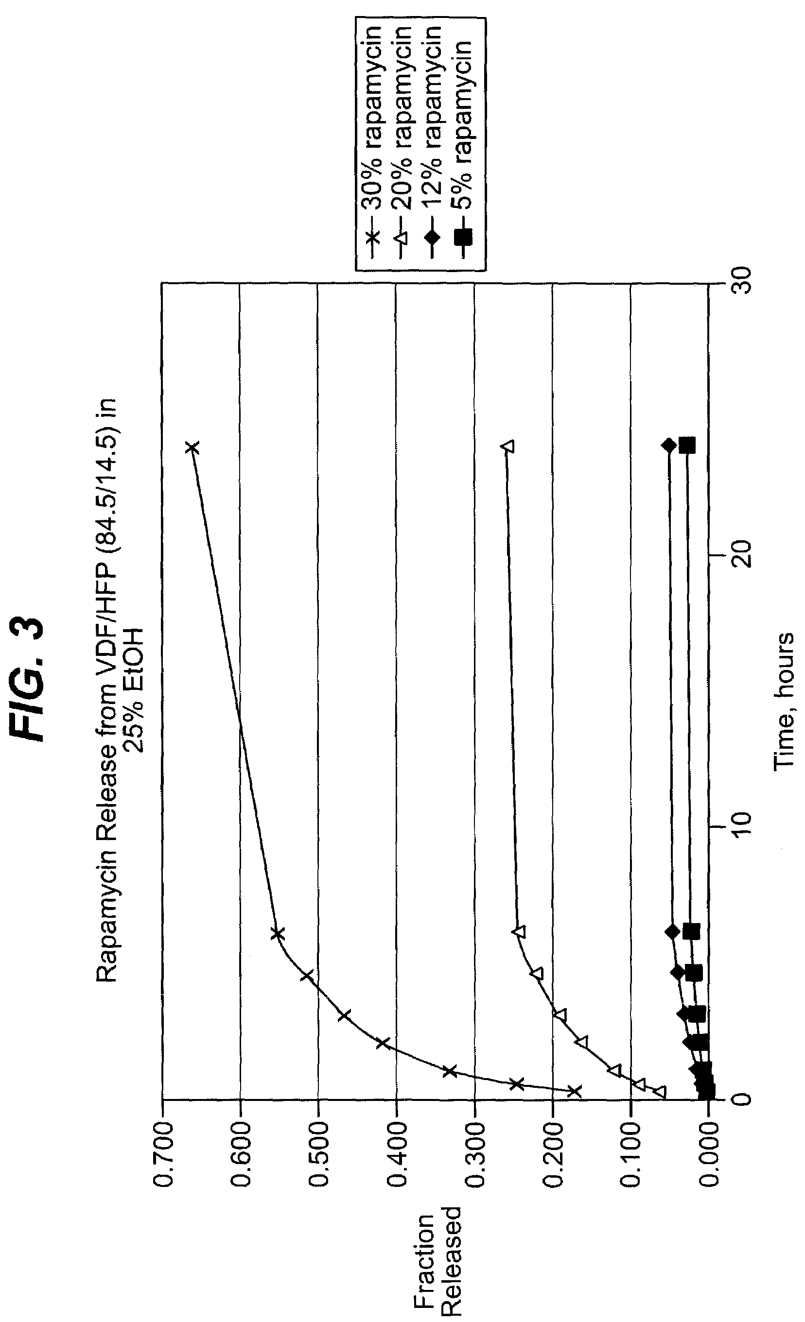
[0121]Polyfluoro copolymers of still higher HFP content were then examined. This series of polymers were not semicrystalline, but rather are marketed as elastomers. One such copolymer is Fluorel™FC2261Q (from Dyneon, a 3M-Hoechst Enterprise, Oakdale, Minn.), a 60.6 / 39.4 (wt / wt) copolymer of vinylidenefluoride / HFP. Although this copolymer has a Tg well below room temperature (Tg about minus twenty degrees C.) it is not tacky at room temperature or even at sixty degrees C. This polymer has no detectable crystallinity when measured by Differential Scanning Calorimetry (DSC) or by wide angle X-ray diffraction. Films formed on stents as described above were non-tacky, clear, and expanded without incident when the stents were expanded.

[0122]The coating process above was repeated, this time with coatings comprising the 60.6 / 39.4 (wt / wt) (vinylidenefluoride / HFP) and about nine, thirty and fifty weight percent of rapamycin (Wyeth-Ayerst Laboratories, Philadelphia, Pa.), based on total weight...


PUM


Abstract

Medical devices, and in particular implantable medical devices, including self-expanding stents, may be coated to minimize or substantially eliminate a biological organism's reaction to the introduction of the medical device to the organism. The devices utilized to deliver the implantable medical devices may be modified to reduce the potential for damaging the implantable medical device during deployment.

Description

BACKGROUND OF THE INVENTION[0001]1. Field of the Invention[0002]The present invention relates to the local administration of drug / drug combinations for the prevention and treatment of vascular disease, and more particularly to intraluminal medical devices for the local delivery of drug / drug combinations for the prevention and treatment of vascular disease caused by injury and methods and devices for maintaining the drug / drug combinations on the intraluminal medical devices, as well as preventing damage to the medical device. The present invention also relates to medical devices, including stents, grafts, anastomotic devices, perivascular wraps, sutures and staples having drugs, agents and / or compounds affixed thereto to treat and prevent disease and minimize or substantially eliminate a biological organism's reaction to the introduction of the medical device to the organism. In addition, the drugs, agents and / or compounds may be utilized to promote healing.[0003]2. Discussion of the...

Claims


Application Information

Patent Timeline
Patent Type & Authority Patents(United States)
IPC IPC(8): A61F2/06A61F2/84A61F2/82
CPCA61F2/958A61F2002/9665
Inventor HOUGHTON, MICHAEL J.MAJERCAK, DAVID C.
Owner CARDINAL HEALTH SWITZERLAND 515 GMBH
Why Eureka
Try Eureka