Compact non-contact multi-function electrical switch

a capacitance switch, non-contact technology, applied in the direction of relays, pulse techniques, lighting and heating apparatus, etc., can solve the problems of increasing costs and complexity, reducing the capacitance in front of the sensor, and clearly not being able to replace the mechanical wall mounted switch as a direct replacement, etc., to achieve the effect of increasing the component count and overall device size and complexity, reducing the sensitivity of the sensor, and increasing the capacitan

Inactive Publication Date: 2009-05-12
CENCUR MARKO
View PDF5 Cites 55 Cited by
  • Summary
  • Abstract
  • Description
  • Claims
  • Application Information

AI Technical Summary

Benefits of technology

[0043]Another advantage of the present invention is that it does not use absolute predetermined values of capacitance to control the switch. With the '608 patent device, to turn the switch fully on, the hand has to come into the closest zone to the sensor. Since this zone is fixed, it could be inside the wall, for example if the sensor is mounted too deeply into a wall recess or if the sensor is covered by a cover plate that is too thick. In both cases it would be impossible to turn the switch fully on since the closest sensor zone would be inaccessible. A similar problem could occur if a permanent conductive object were mounted near the '608 sensor. This surface would distort the electrical field of the sensor resulting in reduced sensor sensitivity, as zones become closer to the sensor surface. Both problems could possibly be overcome by setting the sensor parameters manually or automatically. If the sensor parameters are adjusted manually, each user of the switch would be responsible for these settings, which is a significant drawback since this would complicate installation. For automatic sensor adjustment, special circuitry must be added to the sensor since the '608 device is not capable of auto-calibration, increasing component count and overall device size and complexity.
[0044]In the inventive switch, this problem is solved by reacting on the capacitance change rather than on the absolute value. The flag for detecting the presence of an object is set when capacitance in front of the sensor is increased. There is no fixed predetermined level at which presence is detected. By this the switch is also self-calibrated, as it cancels out any permanent capacitance changes in front of the sensor. This auto-calibration may be implemented completely in software without any increase in component count or in the size of the inventive switch.
[0045]The present invention operates independent of hand speed and no special moves are necessary in front of the sensor to activate the basic function of the switch. It always changes the state if the hand is put near the sensor, and then after, particular directional movements of the hand and positions of the hand can be programmed for activating particular functions, i.e., up for increasing power, down for decreasing power, left to right to activate a second circuit, right to left, to deactivate the second circuit, etc.

Problems solved by technology

In addition, the dimming function is achieved in defined steps which require particular components for each step, further increasing costs and complexity.
To users unfamiliar with the device this could result in confusion.
The device is clearly not capable of functioning as a direct replacement of a mechanical wall mounted switch.
The device also requires both a neutral and a live connection to the AC power source, while in many wall boxes and circuit designs, only one lead is accessible, rendering such a device useless as a direct replacement.
A particular problem with the prior art is the inability to provide a direct replacement for a mechanical switch.
Utilizing special size boxes or special wiring adds substantially to the cost of installation, and is prohibitive in any retrofit application.
However, it was found that the switches described in the previous patent were somewhat difficult to mount close together in a gang installation.
If they are too close, the sensor ranges may overlap and then it becomes difficult to activate just a single switch without activating neighboring switches by accident.
While this problem can be overcome by reducing the sensor ranges, this may also reduce the usability of the switch.
Another problem that may occur in a ganged installation relates to the capacitive sensors.
If the capacitive sensors in adjacent switches operate as oscillators, pulse generators or any other changing voltage / current method that measures sensors impedance, they can interfere with each other.
If the sensors are close together, and their frequency is similar, they can “tune” to each other, just as a radio tunes to a transmitter frequency, and when that occurs, the sensors can interfere so the switches won't work correctly.
While this can be overcome by reducing the range of the sensor or by shielding the sensor field, both solutions may degrade somewhat switch usability.

Method used


Image

  • Compact non-contact multi-function electrical switch
  • Compact non-contact multi-function electrical switch
  • Compact non-contact multi-function electrical switch

Examples


Embodiment Construction

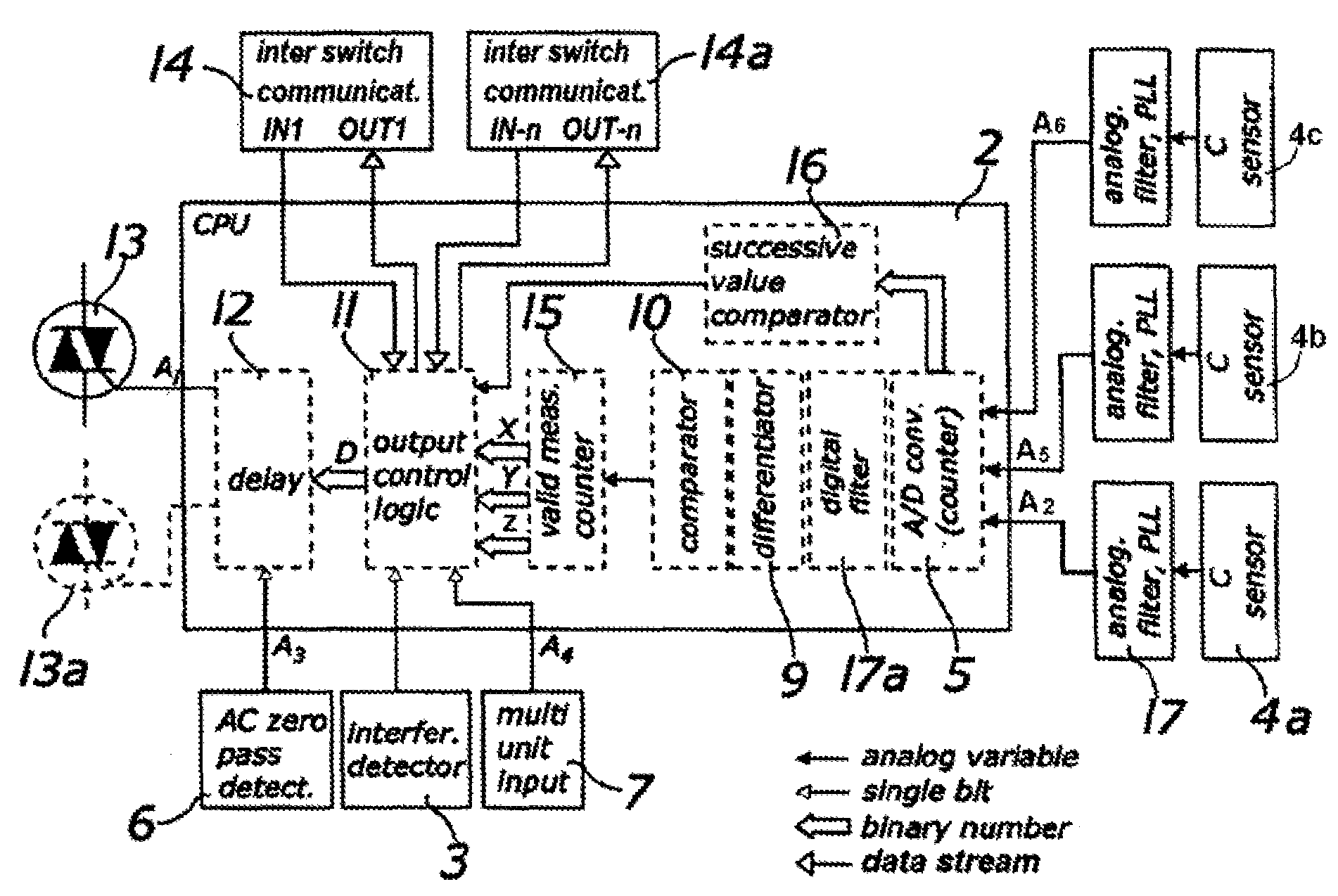
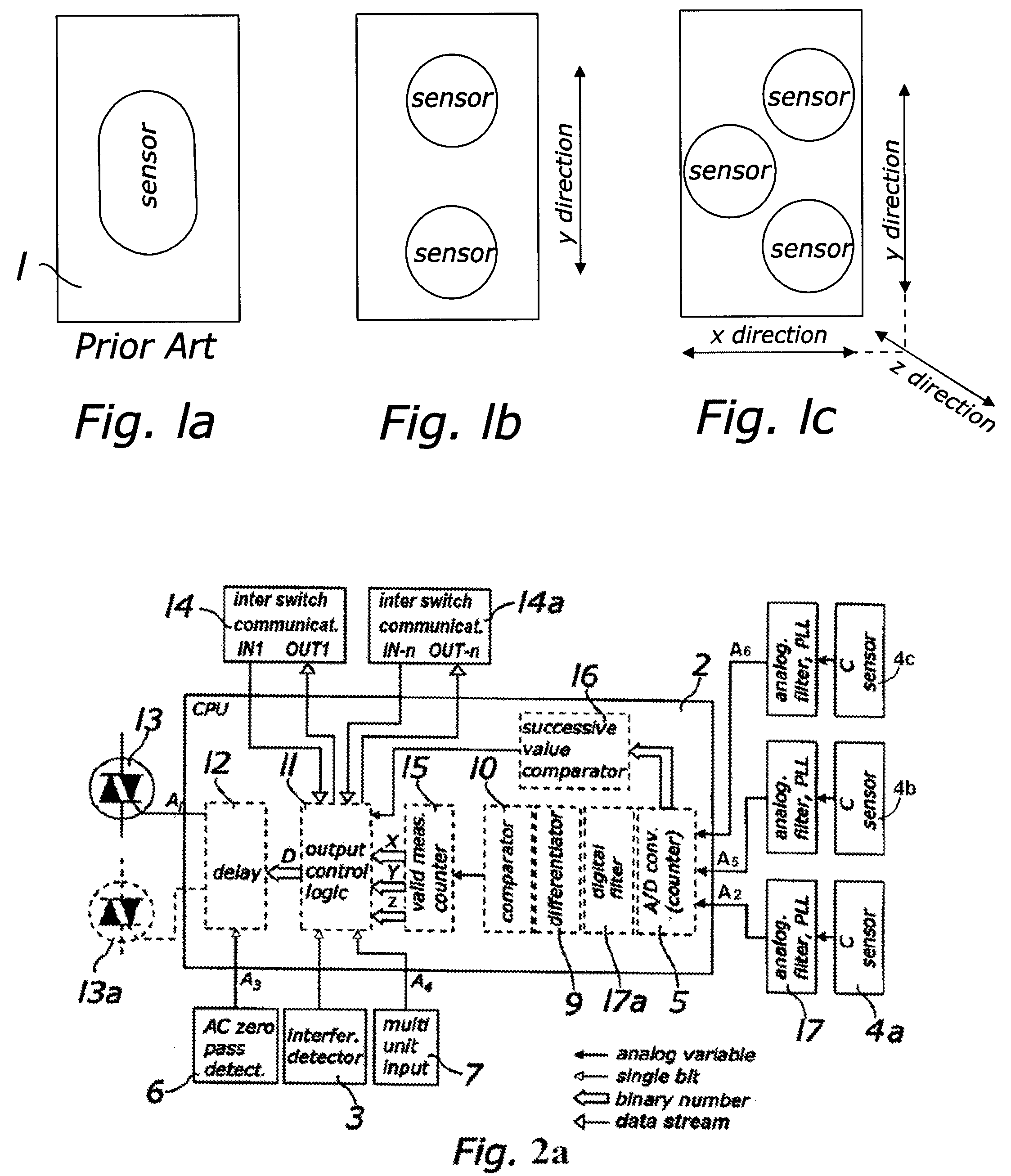
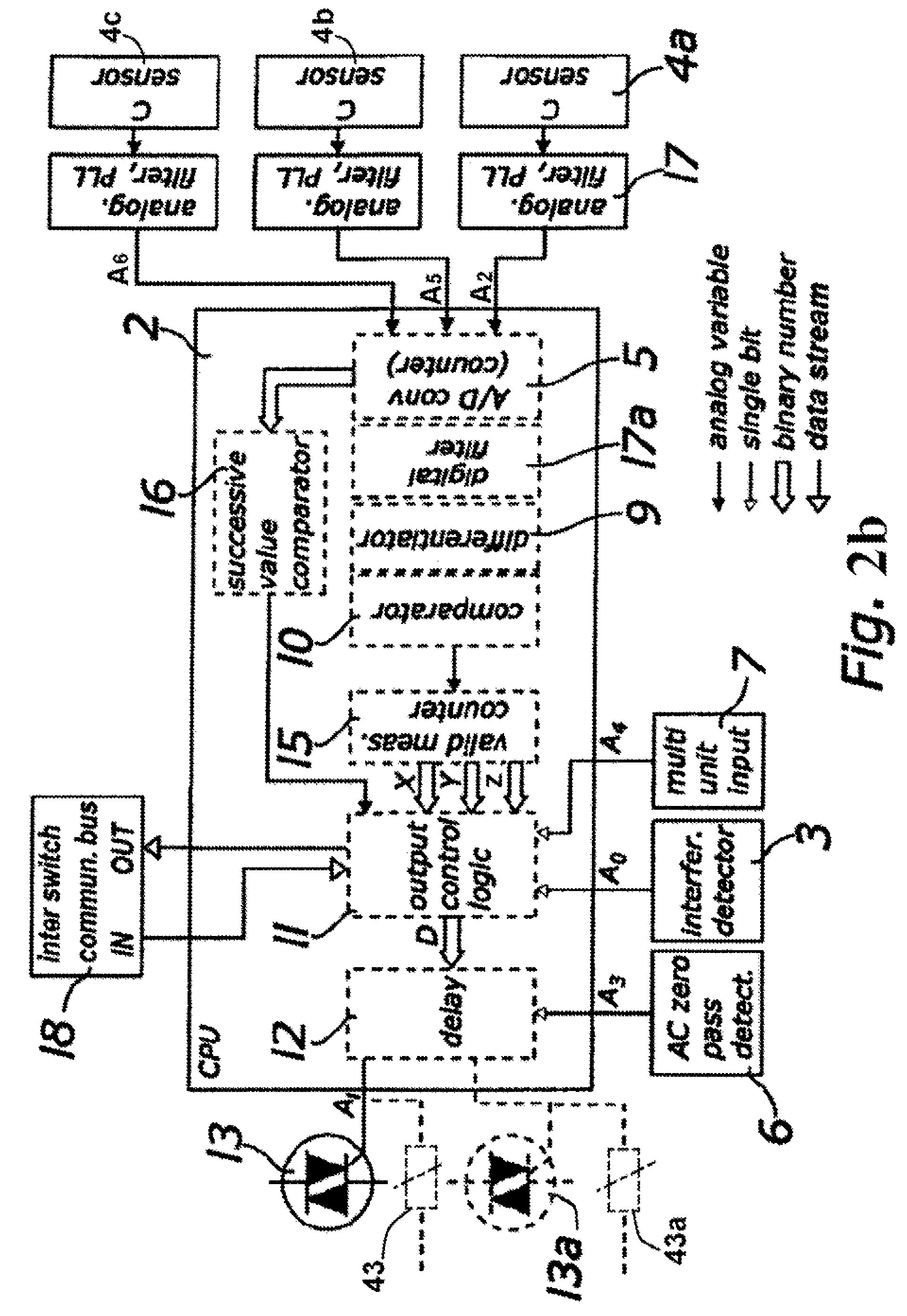
[0055]To construct the inventive switch for use in a standard wall box and to meet all international standards, the switch must be as compact as possible. The number and size of components must be minimized, as well as the number of data lines between elements of the circuit and the space occupied by inter-component connections to reduce the number of chip-pin count, reducing chip size.

[0056]Some of the elements used in the switch (triac, snubber capacitor for triac, filter choke, power supply, fuse) are basic and are conventionally used in many types of electronic devices. Since they are quite bulky, they also would normally decrease useful space for specialized electronic parts such as the capacitive sensor, control circuitry, back lighting, etc.

[0057]Previously, it was thought that to achieve a compact integral design, it was necessary to detect only the presence of an object such as a hand placed in front of the sensor rather than its position relative to the sensor. This produc...


PUM


Abstract

A compact non-contact multi-function electrical switch for use in an electrical box mounted on a wall has a one or more capacitance sensors for detecting a presence of a hand placed adjacent to the switch, as well as the directional movements of the hand along an X and / or Y axis and / or Z axis, and for generating data values, and a CPU for receiving the values and for determining which function is to be performed, such as calculating a power output in response to a first data bit. The switch can communicate with nearby switches to avoid sensor interference. The CPU can be used to generate one or more control signals for controlling the predetermined function associated with the specific movements. A processing unit may be used with multiple switches in a gang assembly, so that the switch sensors form an array enabling the switches to perform more complex control functions.

Description

TECHNICAL FIELD[0001]This invention relates to electrical switches and more particularly to a compact non-contact multi-function capacitance switch for control of one or more electrical circuits.BACKGROUND[0002]Most household or office electrical circuits, particularly those related to lighting, typically utilize mechanical switches. These mechanical switches may be of the contact type for on / off activation, or include a means for varying the power supplied to the circuit, i.e., to perform a “dimming” function, to variably alter power supplied to a light or to act as a speed control for a fan.[0003]Non-contact switches that rely on a change in capacitance to perform an on / off function have been proposed. These devices sense the presence or absence of an object in front of the switch by the change in capacitance.[0004]In U.S. Pat. No. 5,973,608, a non-contact switching system is described that utilizes selected components to provide on / off and dimming functions. However, the componen...

Claims


Application Information

Patent Timeline
Patent Type & Authority Patents(United States)
IPC IPC(8): H01H47/00H02H3/42
CPCH03K17/955H03K2217/94052H03K2217/94094
Inventor CENCUR, MARKO
Owner CENCUR MARKO
Why Eureka
Try Eureka