Apparatus and method for oxidation and stabilization of polymeric materials

Inactive Publication Date: 2009-05-19
UT BATTELLE LLC +2
View PDF24 Cites 39 Cited by
  • Summary
  • Abstract
  • Description
  • Claims
  • Application Information

AI Technical Summary

Benefits of technology

[0018]Objects of the present invention include the following: providing an apparatus for oxidizing and stabilizing thermoplastic materials prior to carbonization; providing an apparatus for more rapid and cost-effective treatment of PAN fibers by exposure to reactive oxidative species; providing a method for oxidation and stabilization of polymeric materials that is faster and requires less physical space; providing a method for stabilizing PAN fibers that creates a more uniformly stabilized fiber that can yield a more uniform product after carbonization; and, providing a method of polymer stabilization in which the polymer is contacted by a diffuse plasma in order to avoid the deleterious effects of a concentrated or filamentary plasma on the polymer. These and other objects and advantages of the invention will become apparent from consideration of the following specification, read in conjunction with the drawings.
[0019]According to one aspect of the invention, an apparatus for treating polymeric materials comprises: a treatment chamber adapted to maintain a selected atmosphere; a source of plasma-derived gas containing at least one reactive oxidative species; and, a means for supporting the polymeric material within the chamber at a location wherein the polymer will not contact a filamentary plasma discharge but will

Problems solved by technology

Traditionally, the first oxidation or stabilization processing step is the most time-consuming and rate-limiting step in conventional carbon fiber manufacturing, and it requires more space than all other steps combined.
That work was independent of precursor material, but is limited to the carbonization and graphitization of materials that already have bee

Method used


Image

  • Apparatus and method for oxidation and stabilization of polymeric materials
  • Apparatus and method for oxidation and stabilization of polymeric materials
  • Apparatus and method for oxidation and stabilization of polymeric materials

Examples


example 1

Vacuum Pressure Plasma Processing

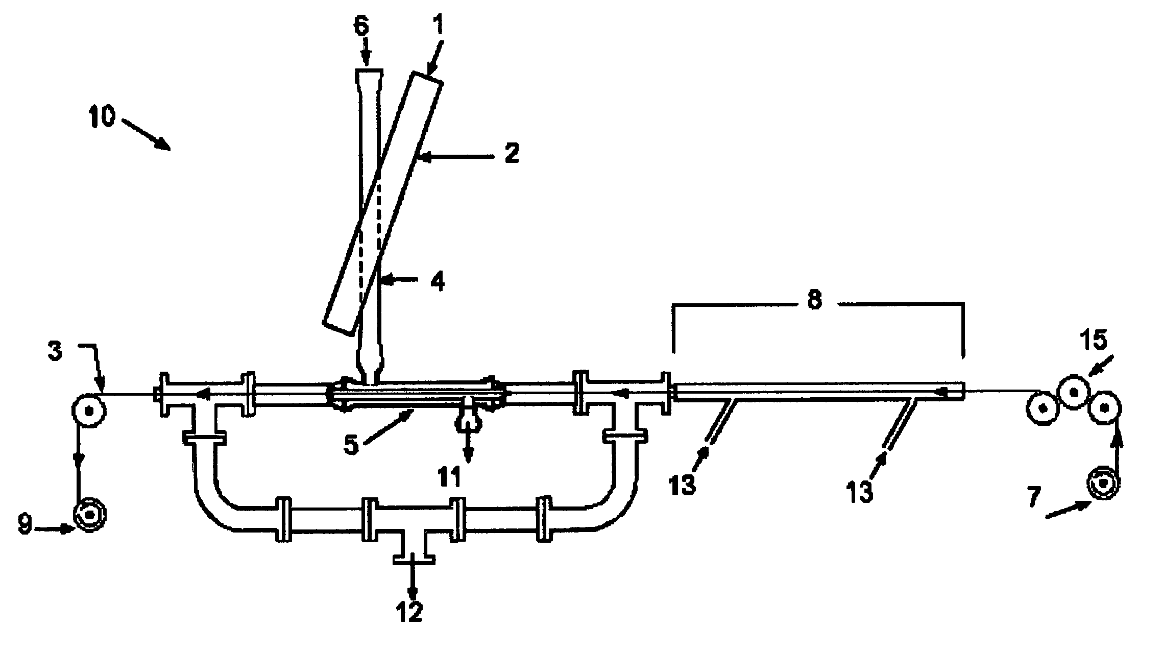
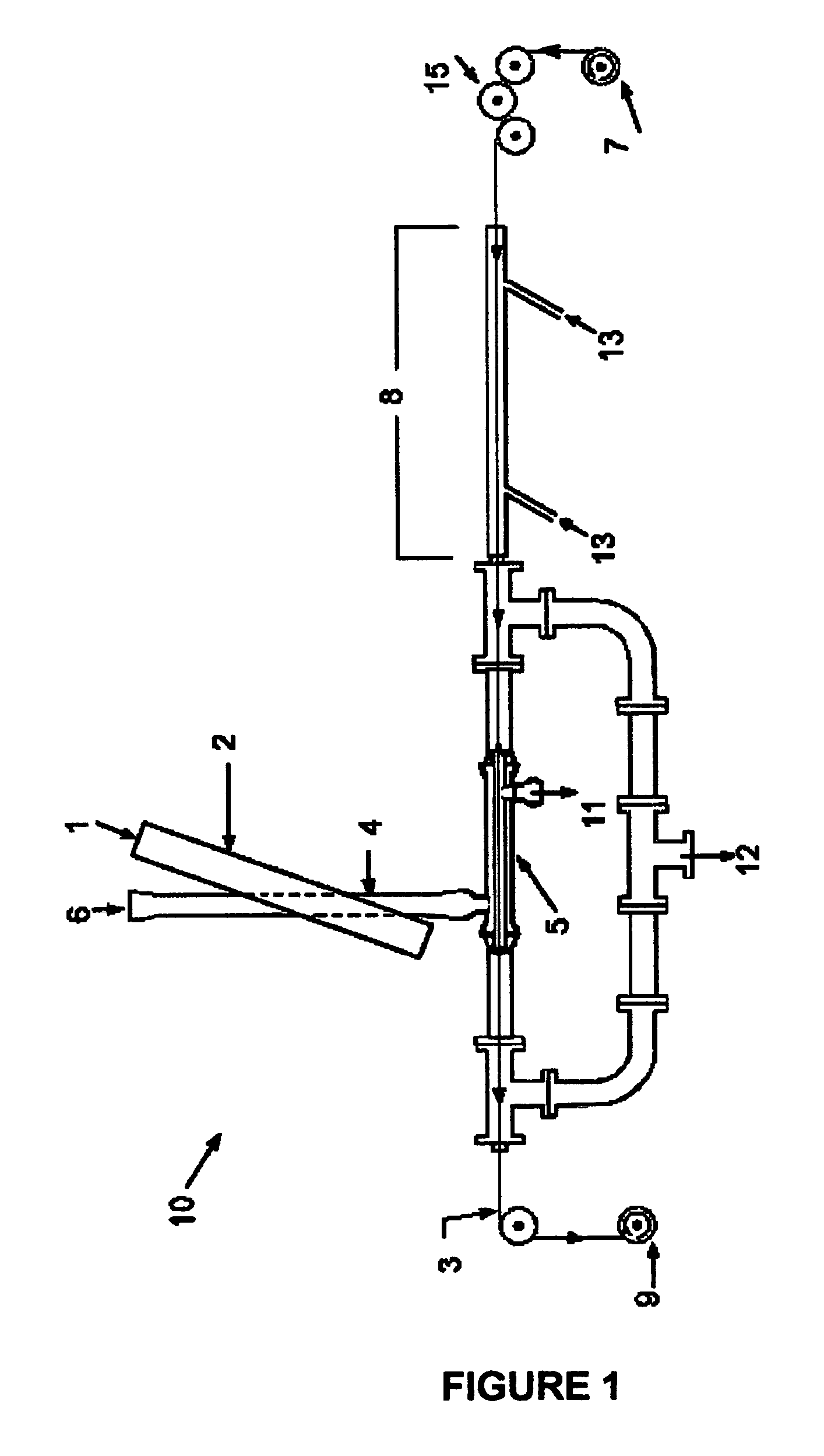
[0052]The general setup for vacuum-based microwave glow discharge plasma treatment system shown at 10 in FIG. 1 consists of several different interconnected components including a microwave plasma generator 4, an applicator 5, a vacuum system, and a fiber transport system. A microwave generator supplies microwave power at 1 into a shorted waveguide 2 through which a quartz tube passes. The inlet process gases are introduced at 6. These gases, after being ionized by the plasma to form ROS, are fed to the applicator 5, which is a reaction chamber located downstream from the bulk of the plasma volume. This quartz reactor employs conventional connections for vacuum and connections at the other end for the supply of the ROS required for the processing. Several ROS applicators 5 were designed and tested with sequential improvements in the processing capabilities with each new design. The preferred design is illustrated in FIG. 4. The operating inlet gases ...

example 2

Atmospheric Pressure Plasma Processing

[0068]A variety of atmospheric pressure plasma devices have been built during the course of the present research effort. These devices are generally based on the approach taught in U.S. Pat. Nos. 5,387,842 and 5,414,324. These devices have consisted of various parallel electrode designs that have included parallel plates and rods. In these designs either one or both of the electrodes are insulated. The processing gas and PAN fiber was fed through a gap or spacing between the electrodes. The electrodes were energized with an audio frequency power supply and operated in such a manner as to promote a diffuse dielectric barrier type discharge.

[0069]The atmospheric pressure plasma processing equipment consists of a gas supply system, a plasma reactor, and a high voltage power supply as shown in FIG. 3. The gas supply system consists of a gas manifold 39 with connections for up to four different gas bottles 37 (two of which are shown) with independent...

example 3

Variant Atmospheric Plasma Processing Designs and Methods

[0080]There are many possible ways of delivering the ROS from the plasma to the thermoplastic material. These designs can be categorized by either placing the fiber within or outside of the plasma discharge that is either volumetrically generated between two electrodes or a surface discharge such that the plasma is a thin volume of plasma above a surface of dielectric. Those skilled in the art will appreciate that the new process may alternatively be accomplished by placing the polymer in the vicinity immediately outside of the plasma volume as well as within the smaller volume of a surface discharge. The advantage of placement in close proximity but not within a plasma discharge is that the plasma could be operated at even higher energy levels that would otherwise create unacceptable amounts of detrimental etching of the fiber. These higher energy levels would allow for greater concentrations of ROS and promote more rapid oxi...


PUM

PropertyMeasurementUnit
Temperatureaaaaaaaaaa

Abstract

An apparatus for treating polymeric materials comprises a treatment chamber adapted to maintain a selected atmosphere; a means for supporting the polymeric material within the chamber; and, a source of plasma-derived gas containing at least one reactive oxidative species whereby the polymer is stabilized and cross linked through exposure to the oxidative species in the chamber at a selected temperature. The polymer may be directly exposed to the plasma, or alternatively, the plasma may be established in a separate volume from which the reactive species may be extracted and introduced into the vicinity of the polymer. The apparatus may be configured for either batch-type or continuous-type processing. The apparatus and method are especially useful for preparing polymer fibers, particularly PAN fibers, for later carbonization treatments.

Description

CROSS REFERENCE TO RELATED APPLICATION[0001]This application claims the benefit of Provisional Patent Application Ser. No. 60 / 666,301 filed by the present inventors on Mar. 29, 2005, the entire disclosure of which is incorporated herein by reference.STATEMENT REGARDING FEDERALLY SPONSORED RESEARCH[0002]This invention was made with Government support under Contract No. DE-AC05-000R22725 awarded by the U.S. Department of Energy to UT-Battelle, LLC, and the Government has certain rights in this invention.BACKGROUND OF THE INVENTION[0003]1. Field of the Invention[0004]The invention pertains to apparatus and methods to treat polymeric materials, and more particularly to systems and methods for plasma assisted oxidation and stabilization of thermoplastic materials in preparation for high-temperature carbonization.[0005]2. Description of Related Art[0006]The production of carbon fibers from thermoplastic-based fibers, e.g., polyacrylonitrile (PAN), is typically a multi-step process in whic...

Claims


Application Information

Patent Timeline
IPC IPC(8): C08F6/00C08J3/00
CPCB29C59/14C08J3/24D06M10/06D01F9/225B29C2059/145B29K2033/20Y10T428/24942D01F9/14D06M2101/28C08J2333/20Y10T428/31663
Inventor PAULAUSKAS, FELIX L.WHITE, TERRY L.SHERMAN, DANIEL M.
Owner UT BATTELLE LLC
Why Eureka
Try Eureka