Magnetic head with air bearing surface protection film and manufacturing method thereof

a technology of protective film and magnetic head, which is applied in the manufacture of head surfaces, maintaining head carrier alignment, instruments, etc., can solve the problems of sliding resistance and corrosion resistance exceeding a certain level of effect, and achieve the effect of reducing the thickness of the protective film and the thickness of the film

Inactive Publication Date: 2009-06-23
WESTERN DIGITAL TECH INC
View PDF11 Cites 4 Cited by
  • Summary
  • Abstract
  • Description
  • Claims
  • Application Information

AI Technical Summary

Benefits of technology

[0022]The tetrahedral-amorphous carbon constituting the uppermost surface (uppermost portion) of the air bearing surface protective film of the magnetic head manufactured by the method according to an embodiment of the invention as described above is a thin carbon film with a required minimum thickness for constituting the tetrahedral structure (SP3) (lattice constant) of 3.5 Å or more and with a mass density of from about 2.5 to 3.4 g•cm3. On the other hand, the amorphous carbon with low mass density in which the mass density of the thin carbon film constituting a surface (portion) of the bearing surface protective film in contact with the magnetic device is made lowest is a carbon film with a mass density of from about 1.5 to 2.4 g•cm−3 and with the SP3 bonding ratio of less than 50%, in which the required minimum thickness for constituting the trigonal structure is 2.5 Å or more. Further, since the total thickness of the bearing surface protective film of the magnetic head applied at current products is 50 Å, the effect of the invention with an aim of reducing the thickness of the magnetic head protective film can be recognized in the region with the total film thickness of less than 50 Å. Accordingly, to restrict the total film thickness of the tetrahedral-amorphous carbon and the low mass density amorphous carbon to less than 50 Å, a range should be restricted as about 3.5 Å or more and less than about 47.5 Å for the tetrahedral amorphous carbon and as about 2.5 Å or more and less than about 46.5 Å for the low mass density amorphous carbon.
[0023]According to the present invention, the thickness of the air bearing surface protective film of the magnetic head can be reduced. Specifically, film thickness is reduced by not using the thin silicon film as the adhesion layer while adhesion is maintained. Further, a magnetic head is provided which has an air bearing surface protective film only consisting of a thin carbon film while excluding formation of the dead layer to the read / write elements by carbon ion incidence as less as possible, as well as a manufacturing apparatus and a method therefor are provided.

Problems solved by technology

Thus, the sliding resistance and the corrosion resistance exceeding a certain level of effect cannot be expected.

Method used


Image

  • Magnetic head with air bearing surface protection film and manufacturing method thereof
  • Magnetic head with air bearing surface protection film and manufacturing method thereof
  • Magnetic head with air bearing surface protection film and manufacturing method thereof

Examples


first embodiment

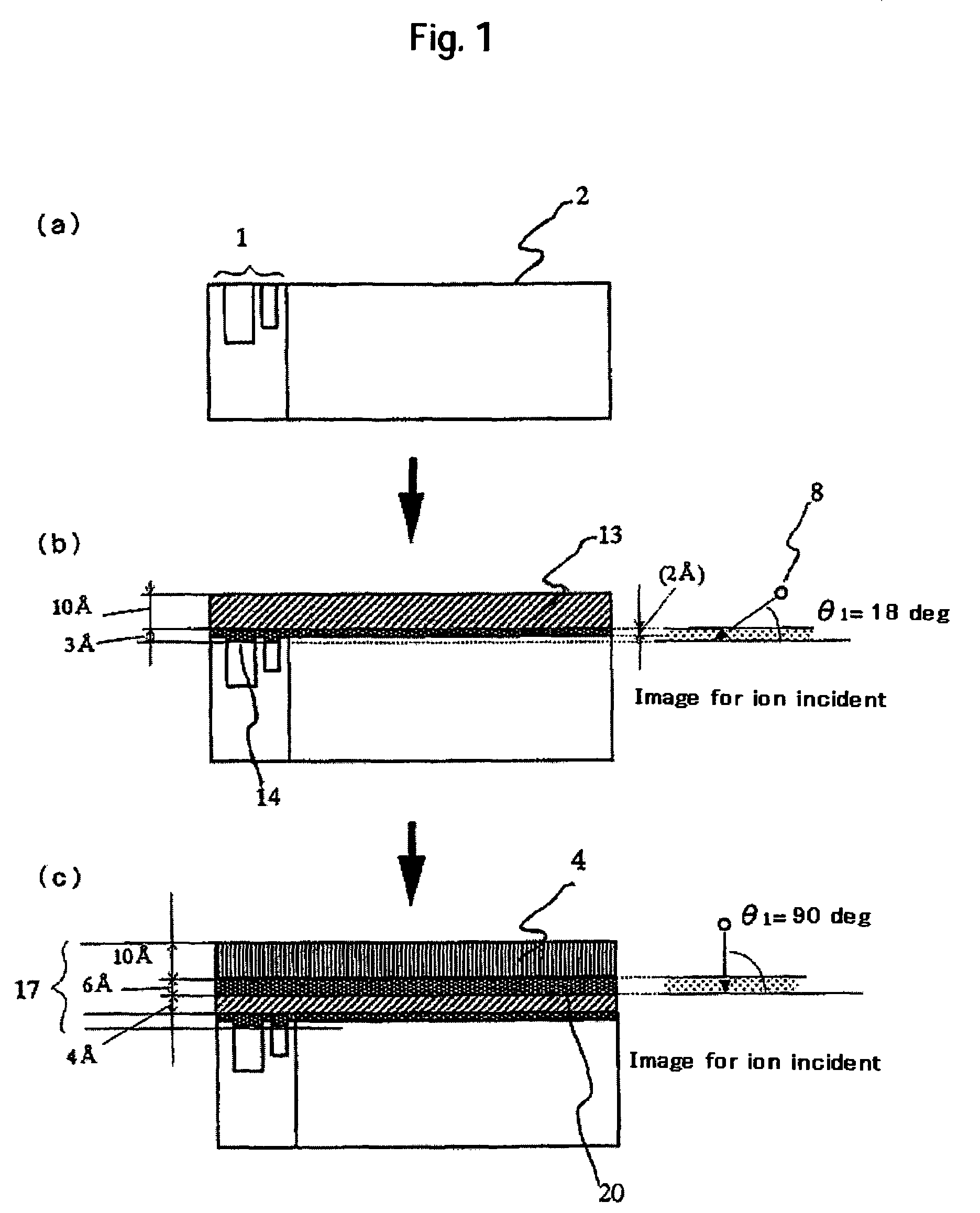
[0040]In accordance with the process flow of the present invention shown in FIGS. 1(a), 1(b) and 1(c), an air bearing surface protective film of a magnetic head is manufactured by a thin film magnetic head manufacturing apparatus in FIG. 6. In a first embodiment of this magnetic head, a low mass density amorphous carbon 13 is formed directly in the manufacturing apparatus of FIG. 6 without using a thin silicon film on an alumina titanium carbide substrate 2 in which a read / write element 1 is formed. As an ion source, an arc plasma source 5 is used. Specifically, when an anode 7 is brought into contact with a graphite cathode 6 connected with an arc power source 32 in the arc plasma source 5, a great amount of thermoelectrons are emitted and electric fields are generated near the cathode 6. Carbon ions 8 jetting out from the cathode 6 by the arc discharge are accelerated to about 50 to 100 eV and a portion thereof passes through a cylindrical magnetic field duct 9 of about 8 inch dia...

second embodiment

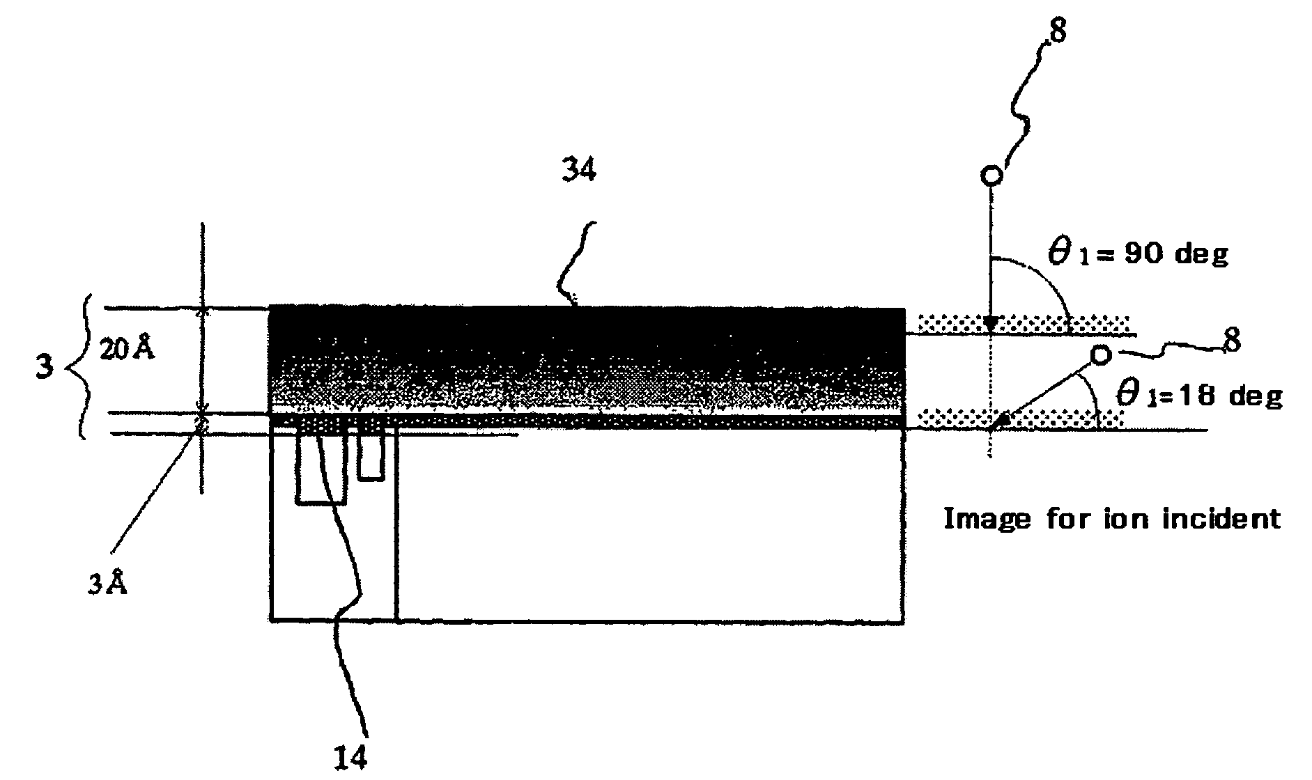
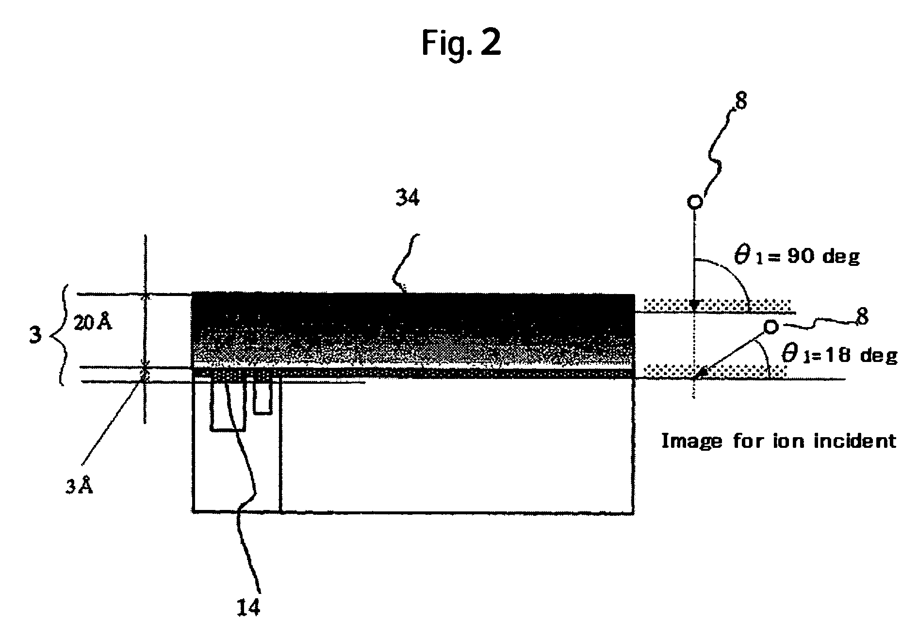
[0051]In the manufacturing method of the first embodiment, the thin carbon film is formed by being divided into two layers by interrupting vapor deposition during change of the incident angle of the carbon ions 8 at about 100 eV from about 18° to about 90° due to control of the vapor deposition rate. However, the vapor deposition can also be conducted continuously during change of the incident angle with no problem by previously measuring the vapor deposition rate. FIG. 2 shows a schematic cross sectional view of a magnetic head slider formed by continuously conducting vapor deposition also during the change of the incident angle. In this schematic view, the mass density of the thin carbon film 34 is depicted by the tint in which a region depicted more densely shows higher mass density. That is, in the initial stage of the vapor deposition, a low mass density thin carbon film is formed on the surface in contact with the magnetic device at about 100 eV with the incident angle of the ...

example 1

[0053]To obtain the same effect as that by the method of forming the thin carbon film of the first and second embodiments, a thin film magnetic head manufacturing apparatus shown in FIG. 7 is also effective. This example 1 provides a thin film magnetic head manufacturing apparatus in which carbon ions 8 are vapor deposited while controlling the incident angle θ1 to the substrate 11 to be processed by an ion flow control mechanism comprising an electromagnet 18 for forming a thin carbon film. A bias voltage application mechanism 19 is connected with the substrate 1 to be processed. In Example 1, the electromagnet 18 is excited at an optional frequency to generate the magnetic fields at a magnetic flux density of 500 to 1000 gauss thereby controlling the incident direction of the carbon ions 8 and enabling radiation to the substrate 11. Instead of example 1, a capacitive coupled electrode may be disposed at a junction portion between the film deposition chamber 10 and the arc plasma s...


PUM

PropertyMeasurementUnit
mass densityaaaaaaaaaa

Abstract

To promote reduction in thickness of an air bearing surface protective film of a magnetic head, a magnetic head having an air bearing surface protective film consisting only of a thin carbon film while excluding formation of a dead layer by ion incidence as less as possible to the read / write device, and a manufacturing method therefore, are provided. In an embodiment, an air bearing surface protective film of a magnetic head comprises a thin carbon film, in which the mass density a lowermost layer of the air bearing surface protective film on the side of a magnetic device is made lower compared with a thin carbon film constituting other adjacent layers. Further, the manufacturing method comprises deposition under the control of time for the incident angle of ion flow to a substrate to be processed and deposition under the control of time for the ion flow energy to a substrate to be processed.

Description

CROSS-REFERENCES TO RELATED APPLICATIONS[0001]This application claims priority from Japanese Patent Application No. JP2004-292133, filed Oct. 5, 2004, the entire disclosure of which is incorporated herein by reference.BACKGROUND OF THE INVENTION[0002]The present invention relates to a magnetic head having both a read element having a magnetic sensor film of a giant magnetoresistive (hereinafter referred to as GMR) type or tunneling magnetoresistive (hereinafter referred to as TMR) type, and a write element using induction magnetic fields generated by carrying electricity to coils, as well as a manufacturing method thereof.[0003]The bearing surface protective film of a magnetic head known so far has a structure obtained by at first forming a thin silicon film by a physical vapor deposition (PVD) method or the like as a stress relaxation layer for improving adhesion with an alumina titanium carbide substrate, and then forming a thin hydrogenated carbon film on the thin silicon film al...

Claims


Application Information

Patent Timeline
Patent Type & Authority Patents(United States)
IPC IPC(8): G11B5/60
CPCG11B5/187G11B5/40G11B5/6005G11B5/3106
Inventor FUJIMAKI, SHIGEHIKOINABA, HIROSHIISHIZAKI, HIROSHI
Owner WESTERN DIGITAL TECH INC
Why Eureka
Try Eureka