Terahertz sensing apparatus using a transmission line

a transmission line and terahertz technology, applied in the field of sensing equipment, can solve the problems of reducing the beam diameter of a propagating terahertz-electromagnetic wave, requiring expensive optical parts with low loss, and difficult to increase the sensitivity of measuring powder materials or liquid materials, etc., to achieve a high degree of freedom for a sample form, high speed, and small size

Inactive Publication Date: 2009-07-21
CANON KK
View PDF31 Cites 21 Cited by
  • Summary
  • Abstract
  • Description
  • Claims
  • Application Information

AI Technical Summary

Benefits of technology

[0012]According to the sensing apparatus and method of the present invention, even in the case of a slight amount of an inspected object, for example, spectral analysis in a region of a millimeter wave to a terahertz wave can be performed at high speed while ensuring a high degree of freedom for a sample form. In such analysis, sensing can be performed for a two-dimensional-shaped inspected object at a high spatial resolution of 100 μm or less. Further, because the small-size sensing chip is used, it is possible to provide the sensing apparatus including the entire optical system, which is small in size and low in cost.

Problems solved by technology

In such a case, there have hitherto been such problems that optical axis alignment is required because a spatial imaging system is used, and that it is hard to increase the sensitivity when measuring a powder material or liquid material.
However, the method using the prism has limitations in reducing the beam diameter of a propagating terahertz-electromagnetic wave, so that there can typically be obtained only a maximum spatial resolution of about 100 μm which corresponds to the order of a wavelength of the terahertz electromagnetic wave.
Further, the use of the prism requires expensive optical parts having low-losses in the THz band, and imposes limitations in size reduction of the entire optical system.
Moreover, since the optical system is liable to be affected by moisture in air, it is necessary to locate the entire optical system in a nitrogen atmosphere, thus hindering the cost reduction.

Method used


Image

  • Terahertz sensing apparatus using a transmission line
  • Terahertz sensing apparatus using a transmission line
  • Terahertz sensing apparatus using a transmission line

Examples


example 1

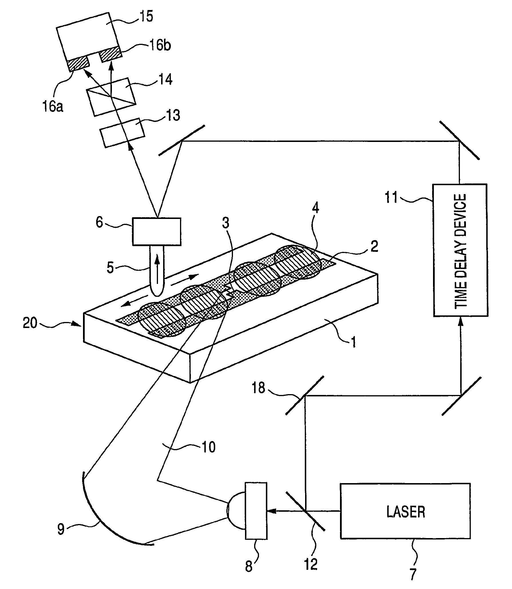
[0024]In a first example of the present invention, a THz sensor chip and a sensing system therefor are provided as shown in FIG. 1. In a sensor chip portion 20, a transmission line 2 of a co-planar strip line structure and an antenna 3, which are made of a Ti / Au electrode, are formed on a Si substrate 1 having a thickness of 650 μm and a high resistance (>1 kΩ-CITi). In this example, the electrode consists of two stripes of 20 μm in width distant by 50 μm from each other. However, the present invention is not limited to this. The antenna 3 is a dipole antenna which is used to efficiently propagate a THz electromagnetic wave 10 irradiated from outside to the transmission line 2. The THz electromagnetic wave 10 may be irradiated from the surface side on which the transmission line 2 is provided. Alternatively, the THz electromagnetic wave may be irradiated from the rear surface side of the substrate 1 because the high resistance Si has a low absorption to the THz electromagnetic wave....

example 2

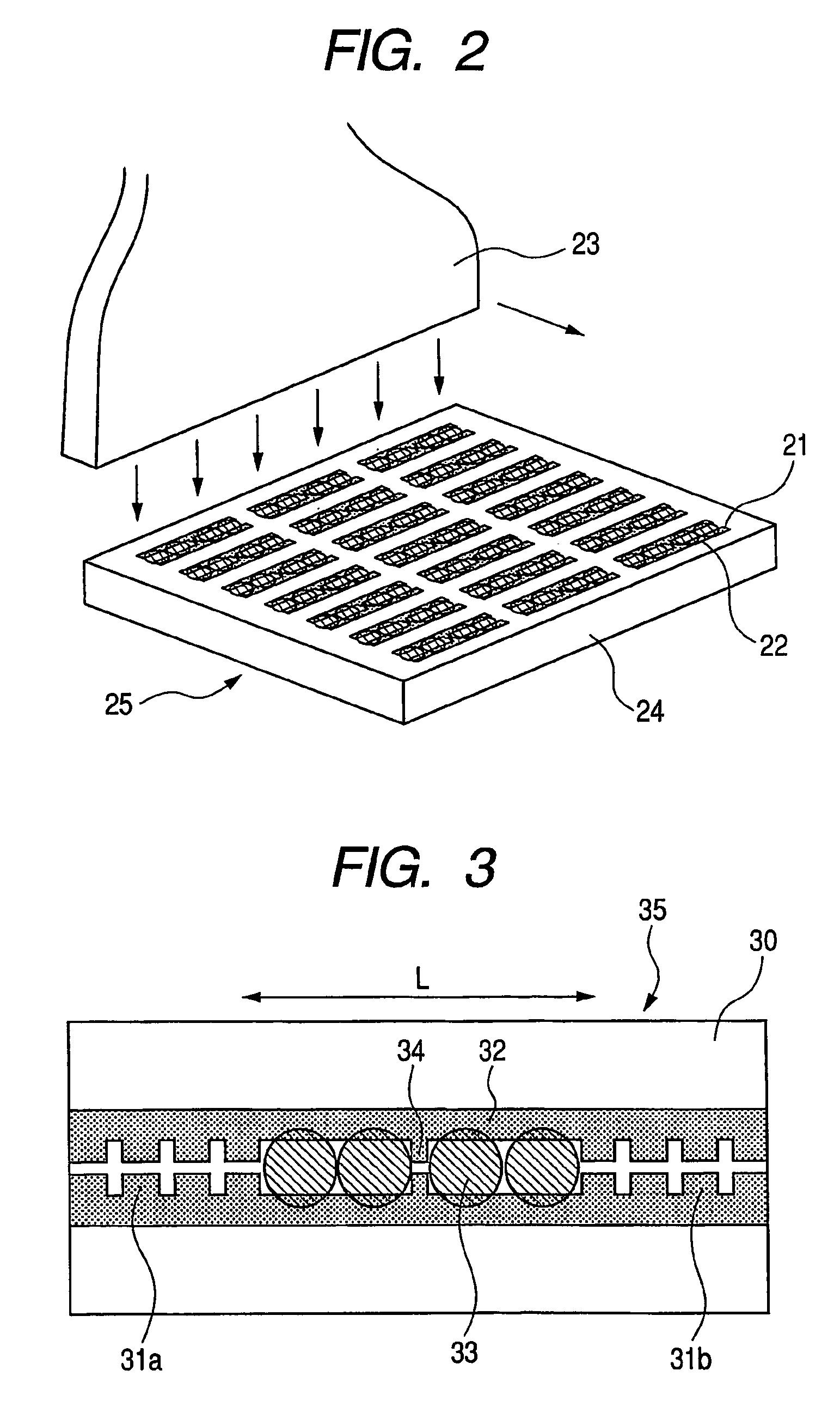
[0033]In a second example of the present invention, distributed reflective regions 31a and 31b having periodic structures are provided in a transmission line 32 on a substrate 30 of a sensor chip 35 as shown in FIG. 3. By adopting such a structure, a specific frequency component of a THz electromagnetic wave irradiated from outside to an antenna 34 is efficiently confined, which is advantageous in the case where high-sensitive measurement is to be performed at a specific frequency.

[0034]FIGS. 4A and 4B are graphical representations showing Fourier spectrum images of an electromagnetic wave in the transmission line 32 in the case where such a structure is adopted. FIG. 4A is for a THz electromagnetic pulse emitted from a photoconductive element such as shown by 8 in FIG. 1. FIG. 4B is for an electromagnetic wave confined in the transmission line in this example. A stop band produced by a DBR reflector corresponds to W, and one or more resonance modes m can be generated within the sto...

example 3

[0037]In a third example of the present invention, unlike the method in which an inspected object is applied to the surface of a sensor chip, an inspected liquid object is caused to flow through a flow path integrally formed with a transmission line as shown in FIG. 5.

[0038]In the example shown in FIG. 5, signal lines 44a, 44b and an insulator 42 are provided on a Si substrate 40 with reference numeral 41 being a ground plane 41 such that a microstrip line is formed as a THz transmission line. Of course, this may be a co-planar strip line such as described in Example 1. The signal lines 44a, 44b are separated from each other by a gap portion 46, under which only an LT-GaAs epitaxial layer is transferred to form a photoconductive element 45 which generates a THz electromagnetic wave pulse by light pulse irradiation. An EO crystal 47 for detecting the transmission state may also be integrated at an end of the transmission line. A flow path 43 having a typical sectional size of 10 μm×2...


PUM

PropertyMeasurementUnit
diameteraaaaaaaaaa
thicknessaaaaaaaaaa
widthaaaaaaaaaa

Abstract

A sensing apparatus is provided which comprises a chip (20) in which a transmission line (2) for propagating an electromagnetic wave is formed on a substrate (1), an electromagnetic wave generator (7) for generating an electromagnetic wave (10), a coupling means (9), and a detector (5) for detecting a propagation state of an electromagnetic wave at an arbitrary location on the transmission line, of the electromagnetic wave propagating through the transmission line (2). An interaction between an object (4) disposed in the vicinity of the transmission line (2) and the electromagnetic wave is detected by the detector (5) to sense a spatial interaction state of the object (4) with the electromagnetic wave.

Description

TECHNICAL FIELD[0001]The present invention relates to a sensing apparatus and method for detecting physical property values or the like of an object using a high frequency electromagnetic wave in a millimeter-wave to terahertz-wave region.BACKGROUND ART[0002]In recent years, nondestructive sensing techniques using an electromagnetic wave o f millimeter-wave to terahertz (THz) frequencies (30 GHz to 30 THz) have been under development. Examples of techniques now under development in “application fields of the electromagnetic wave of such a frequency band include imaging a technique using a safe fluoroscopic apparatus alternative to an X-ray fluoroscope, a spectral technique for obtaining an absorption spectrum or complex dielectric constant of a material to inspect (or examine) the bonding state therein, a technique of analyzing biomolecules, and a technique for estimating a carrier concentration or mobility.[0003]As a sensing system using a terahertz electromagnetic wave, Japanese P...

Claims


Application Information

Patent Timeline
Patent Type & Authority Patents(United States)
IPC IPC(8): G01J5/02G01N21/35G01N21/17G01N21/27G01N21/3586G01N22/00G01N22/02G01Q60/18G01Q60/22G01Q70/06
CPCG01N21/3581
Inventor OUCHI, TOSHIHIKO
Owner CANON KK
Why Eureka
Try Eureka