Method of making an ion transport membrane oxygen separation device

a technology of oxygen separation device and ion transport membrane, which is applied in the direction of cell components, final product manufacturing, sustainable manufacturing/processing, etc., can solve the problems of joule heating and associated thermal stress on the device, and reducing the specific power

Active Publication Date: 2009-09-29
AIR PROD & CHEM INC
View PDF26 Cites 10 Cited by
  • Summary
  • Abstract
  • Description
  • Claims
  • Application Information

AI Technical Summary

Problems solved by technology

Lower resistance leads to lower specific power, which in turns lowers the joule heating and associated thermal stresses on the device.

Method used


Image

  • Method of making an ion transport membrane oxygen separation device
  • Method of making an ion transport membrane oxygen separation device
  • Method of making an ion transport membrane oxygen separation device

Examples


example 1

Co-Sintered Electrochemical Cell Without Slotted Layers

[0084]Green tapes required for multi-layer multi-composition laminates were made from powders that were fabricated by conventional ceramic powder processing techniques starting with the raw oxide components. Each electrode support tape was made as follows: 1000 g of 15 mm diameter YTZ media, 500 g of pre-reacted LCM (La0.4Ca0.6Mn1.01O3−δ) powder possessing a surface area of about 1 m2 / g, 62 g microcrystalline cellulose pore former (NT013), 217.0 g toluene, and 54.3 g ethanol were added to a 1 L HDPE (High Density PolyEthylene) bottle and placed on an industrial paint shaker for ½ hour. 48.7 g of PVB (Poly Vinyl Butyral) B-98 (Solutia brand) binder and 48.7 g of BBP (Butyl Benzyl Phthalate S160) plasticizer were added to the bottle and paint shaken for another hour. The bottle was then placed on a ball mill and allowed to roll at ˜50 RPM for ˜12 hours. This slip was screened through a nylon mesh fabric with ˜40 μm openings, degas...

example 2

Co-Sintered Electrochemical Cell Incorporating Slots in Interconnect

[0097]LCM electrode support tapes (formulated to be porous after sintering), electrode tapes (formulated to be porous after sintering), and electrolyte tapes (formulated to be dense after sintering) described in Example 1 were used to fabricate green multi-layer cells that were then co-sintered. A green electrode tape was prepared from pre-reacted LCM powder that had been milled to a surface area of ˜4.5 m2 / g. The tape was made as follows: 1000 g of LCM powder, 364.8 g of toluene, 91.20 g ethanol, 5 grams PVB B-79, and 1000 g 15 mm Ø YTZ media were added to a 1 liter HDPE bottle. The bottle was paint shaken for ½ hr after which 85.69 g PVB B-98 and 45.34 g BBP S160 were added followed by 1 hr of paint shaking. The bottle was then placed on a ball mill and allowed to roll at ˜50 RPM for ˜12 hrs. The slip was cast on a Mylar carrier film using a doctor blade to make a green ceramic tape.

[0098]Discs (˜4.35 cm diameter)...

example 3

Co-Sintered Single Electrochemical Cell Producing High Purity Oxygen

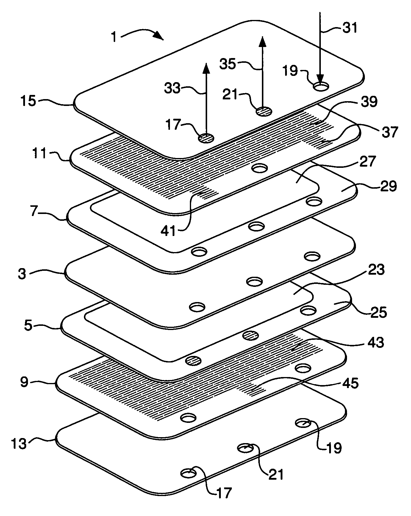
[0101]A green cell was fabricated from green tape layers using the methods described in Examples 1 and 2. The oxygen ion-conducting electrolyte membrane was made from green Ce0.845Sm0.15Co0.005O1.925 tape. Green electrode bi-layers were made by laminating a green tape of 200 micron thick LCM electrode support material to a green tape of 90 micron thick electrode material. The electrode tape used corresponds to composition C in Table 2, in which the ceramic powder was 65 vol % LSCF3728 and the balance Ce0.85Sm0.15O1.925. Electrode rims were made from LCM tape about 250 microns thick and were laminated to the green electrode bi-layers rims to form composite electrode layers, which were then laminated on each side of the electrolyte layer to form a green electrode-electrolyte structure.

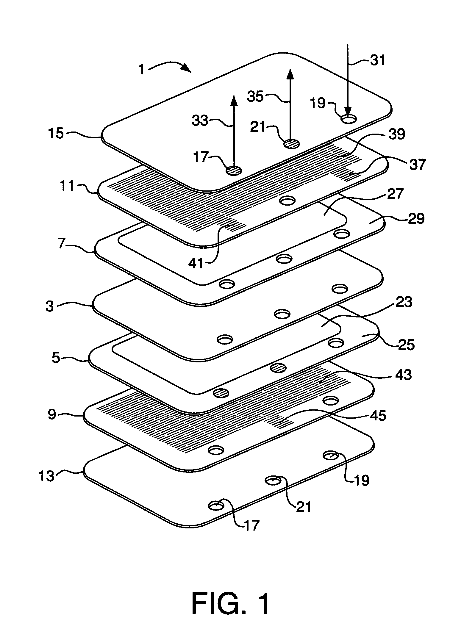
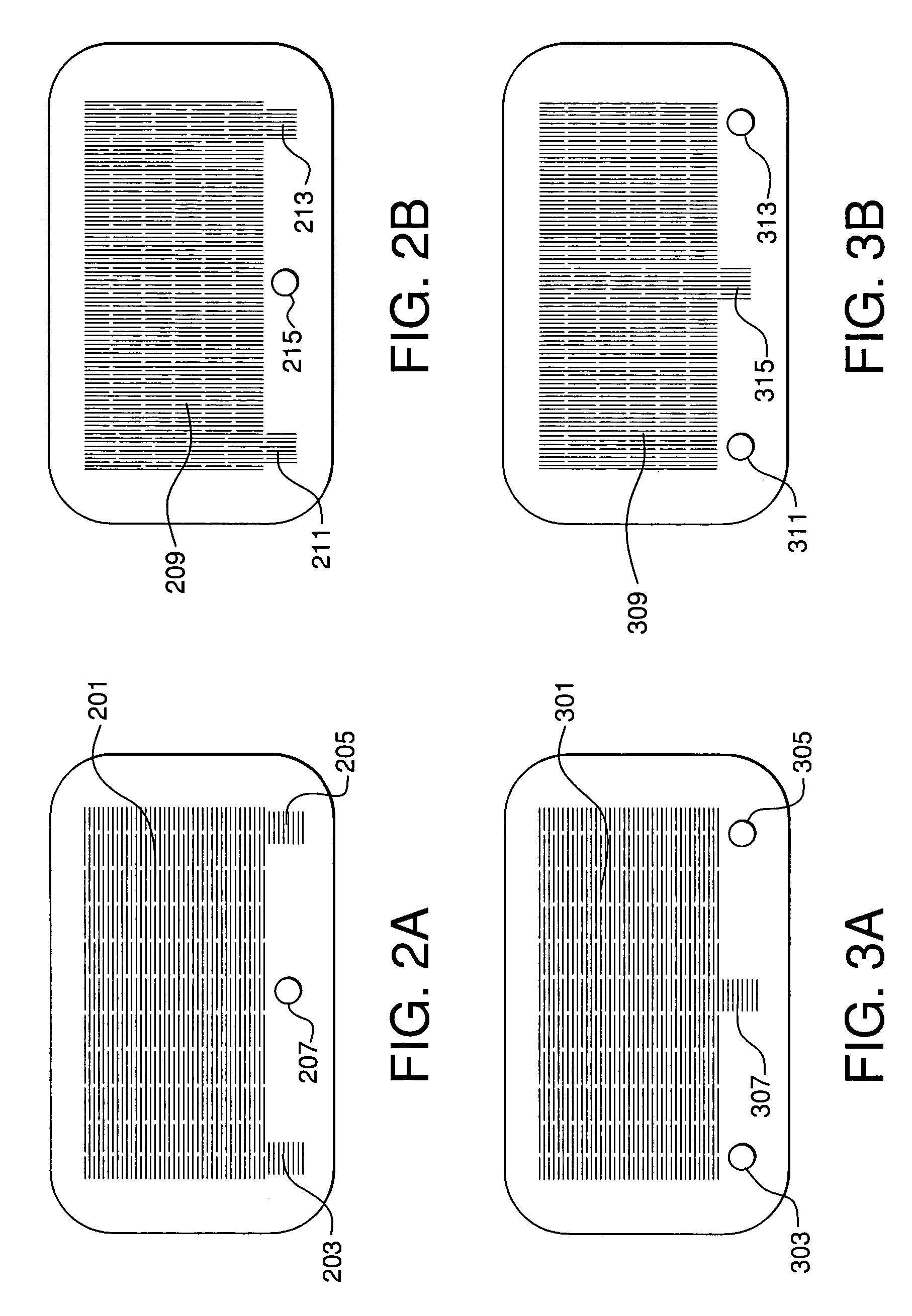
[0102]A cathode side gas distribution interconnect layer was fabricated from two slotted sublayers shown in FIGS. 2A and 2B as describe...


PUM

PropertyMeasurementUnit
temperatureaaaaaaaaaa
pressureaaaaaaaaaa
pressureaaaaaaaaaa

Abstract

Method of making an electrochemical device for the recovery of oxygen from an oxygen-containing feed gas comprising (a) preparing a green electrochemical device by assembling a green electrolyte layer, a green anode layer in contact with the green electrolyte layer, a green cathode layer in contact with the green electrolyte layer, a green anode-side gas collection interconnect layer in contact with the green anode layer, and a green cathode-side feed gas distribution interconnect layer in contact with the green cathode layer; and (b) sintering-the green electrochemical device by heating to yield a sintered electrochemical device comprising a plurality of sintered layers including a sintered anode-side gas collection interconnect layer in contact with the anode layer and adapted to collect oxygen permeate gas, wherein each sintered layer is bonded to an adjacent sintered layer during sintering.

Description

STATEMENT REGARDING FEDERALLY SPONSORED RESEARCH OR DEVELOPMENT[0001]This invention was made with government support under Contract No. F1624-00-C-6000 between Air Products and Chemicals, Inc. and the U.S. Department of Defense. The Government may have certain rights to this invention.BACKGROUND OF THE INVENTION[0002]Electrochemical gas separation devices based on oxygen ion-conducting solid electrolytes have practical applications in the production of high-purity oxygen from air and in the removal of residual oxygen from inert gases such as argon and nitrogen. These devices typically comprise multiple electrochemical cells, each of which is fabricated with multiple layers or components including an electrolyte layer, anode and cathode layers in contact with the electrolyte layer, and interconnect layers in contact with the anode and cathode. The multiple-cell devices may be fabricated into modules designed for the introduction of feed gas into the cells and the withdrawal of permea...

Claims


Application Information

Patent Timeline
Patent Type & Authority Patents(United States)
IPC IPC(8): B28B5/00C25B9/17
CPCH01M4/8621H01M4/8885H01M4/90H01M4/9016H01M8/1226H01M8/126H01M8/242H01M4/9033Y02E60/525Y02E60/521Y02E60/50Y02P70/50H01M8/2483H01M8/2432H01M8/2404
Inventor CUTLER, RAYMOND ASHTONHUTCHINGS, KENT NEALWILSON, MERRILL ANDERSONHOLLIS, RONALD ALMYTAYLOR, DALE M.
Owner AIR PROD & CHEM INC
Why Eureka
Try Eureka