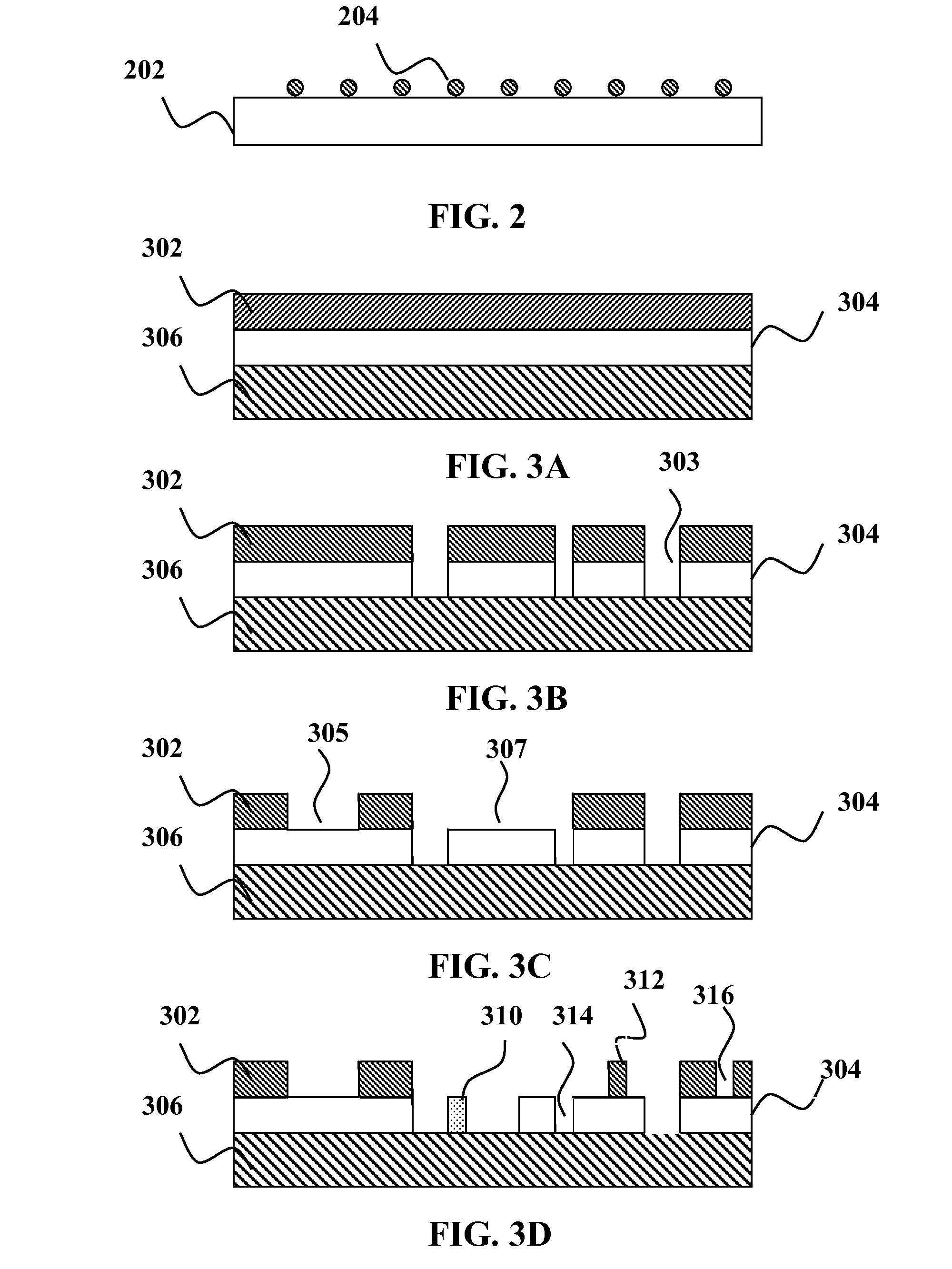
[0022]The use of
ceramic or elemental nanoparticles 204 gives the same performance on the substrate 202 as
polystyrene latex (PSL) spheres with a longer lifetime than
polystyrene latex (PSL) spheres. The degradation of
polystyrene latex (PSL) spheres results when
polystyrene latex (PSL) spheres is exposed to the radiation having the
wavelength less than 260 nanometers. The
high energy photons break the
polymer chains, thus the polystyrene latex (PSL) spheres will physically shrink. Bond strengths in ceramics and elemental materials are substantially higher than bond strengths of polystyrene latex (PSL) spheres, and therefore more resistant to degradation by
exposure to the radiation than polystyrene latex (PSL) spheres of the same size range. Zirconia is a most preferable material because of its ease of deposition and the single valance state of
zirconium. Zirconia (ZrO2) nanopowder is available commercially, e.g., as product number 544760 from Sigma Aldrich, Corporation of St. Louis, Mo.
[0025]The optically transmissive substrate 306 may be made of
quartz. The optically transmissive substrate 306 can be a
photomask blank. Simulated defects may be patterned into the opaque layer 302 and / or the phase shift layer 304 using a pattern generator, e.g. e-beam or
laser. These defects may be defined in a
database used to create the
mask, and therefore their number, location and size may be well controlled. In addition such simulated defects may be easily sized, e.g., using a
Critical Dimension—Scanning
Electron Microscopy (CD-SEM). Fabrication of such masks for contamination mode calibration requires no changes to existing pattern defect
mask design. However, calibrating a contamination mode of an inspection tool with a pattern defect
mask is an entirely new usage for pattern defect masks. In addition, the use of a pattern defect mask for contamination mode calibration is somewhat counterintuitive since the type of defects that best simulate contamination, e.g., defects that are relatively small and not attached to simulated pattern geometry, would not normally be identified as pattern defects in pattern defect mode.
[0027]FIG. 3D shows a step of making simulated defects in the opaque layer 302 and the phase shift layer 304. As shown in FIG. 3D, the simulated defects may include a small piece of phase shift layer material 310 on an exposed portion of the substrate 306, a small piece of opaque layer material 312 on an exposed portion of the phase shift layer 304, a
small hole 314 in the phase shift layer 304 that exposes a portion of the substrate 306, and a
small hole 316 in the opaque layer 302 that exposes a portion of the phase shift layer 304. In addition, the small piece of phase shift layer material 310 may be modified, e.g., by oxidizing or
ion implanting to change its optical properties. Such simulated pattern defects can have a substantially longer lifetime under prolonged UV
exposure than PSL spheres. In addition, control of the size and location of the defects can be made much more precise using simulated defects formed in a pattern defect substrate.
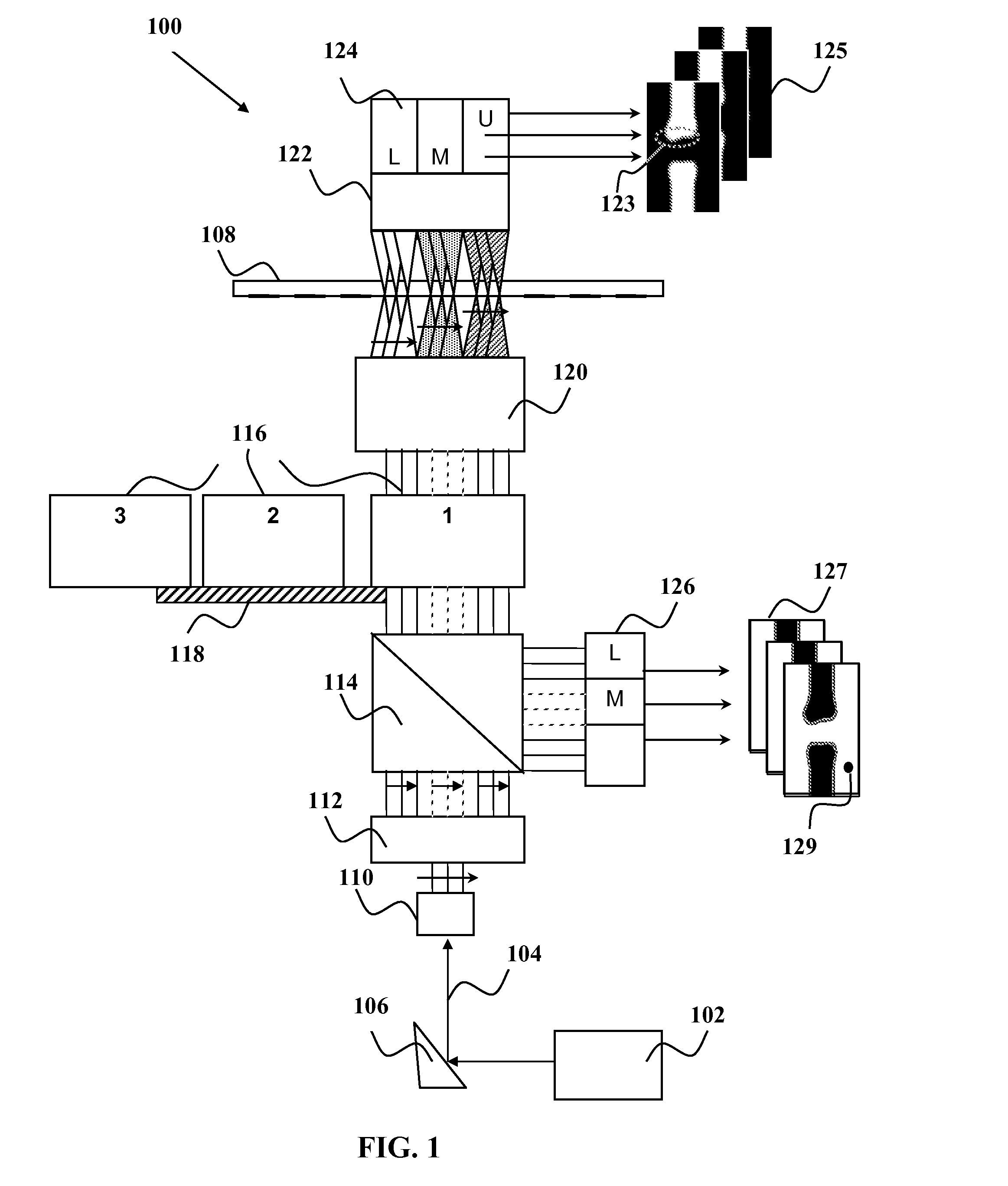
[0029]The
system includes an illumination source 402. By way of example, the illumination source 402 may be a 257-nm wavelength
continuous wave (CW)
laser. An active
beam steering subsystem 404 compensates for beam drift and may also reduce replacement time for the
light source 402. A
transmitted light illuminator 406 may have several different configurations that can be selected by a user at run-time. For example one configuration may implement standard contrast for binary and EPSM reticles. Another configuration may implement phase contrast for
quartz etch reticles such as alternating, chromeless, and the like. The phase contrast mode may provide improved imaging contrast to
quartz phase defects (bumps and divots) allowing higher defect sensitivity.
[0031]The objective 410 images the
reticle surface 409 through a
zoom lens 412 onto an imaging sensor 414. The
zoom lens 412 allows different pixel sizes to be selected by the user at run-time providing different defect sensitivities and associated scan times. Pixel sizes may be of any suitable size including, but not limited to, e.g., 72-nm, 90-nm, 125-nm and 150-nm pixel sizes. By way of example, the imaging sensor 414 may be a time-domain-integration (TDI) sensor. Such a sensor design offers high speed continuous image pick-up at much lower light levels than a conventional
charge coupled device (CCD) linear sensor.
[0034]Embodiments of the present invention allow for calibration of inspection tools with standards that last longer. This reduces the cost and lost productivity associated with having to frequently replace and / or recoat the calibration standard.
