

Passivation layer formation by plasma clean process to reduce native oxide growth
a plasma clean and passivation layer technology, applied in vacuum evaporation coating, lighting and heating apparatus, coatings, etc., can solve the problems of native oxides, difficulty in subsequent fabrication processes, and undesirable native oxide layers
- Summary
- Abstract
- Description
- Claims
- Application Information
AI Technical Summary
Benefits of technology
Problems solved by technology
Method used
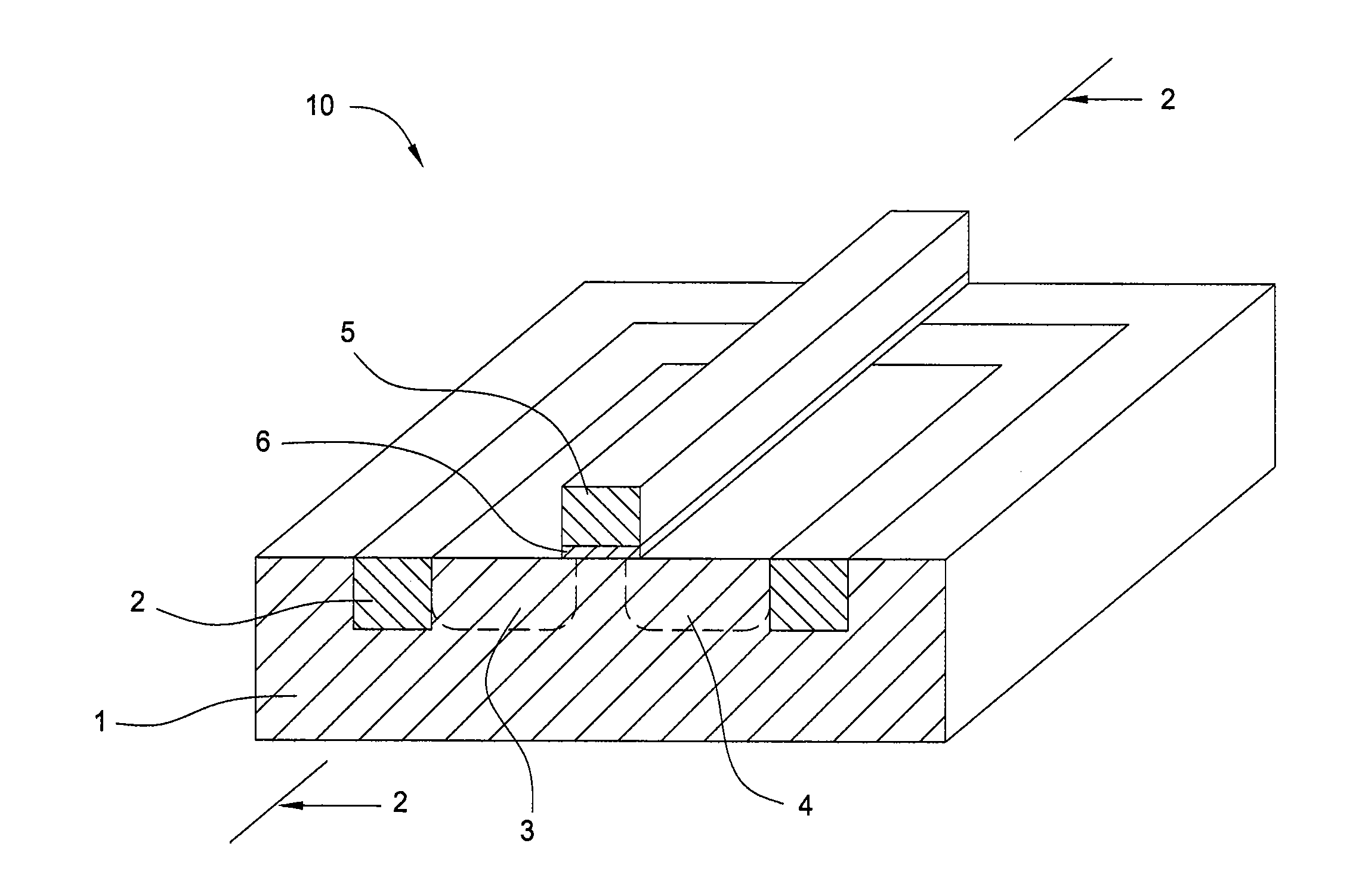
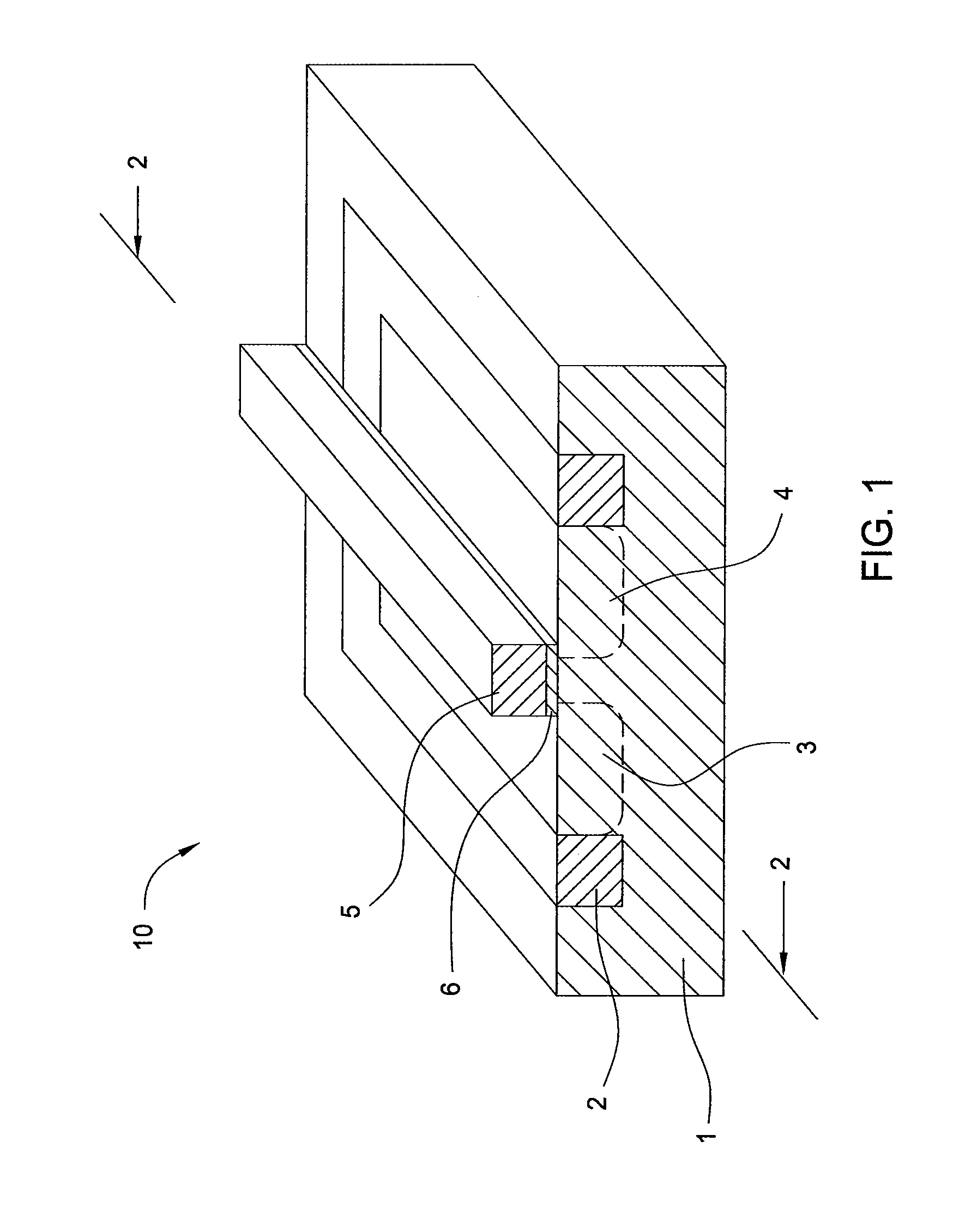
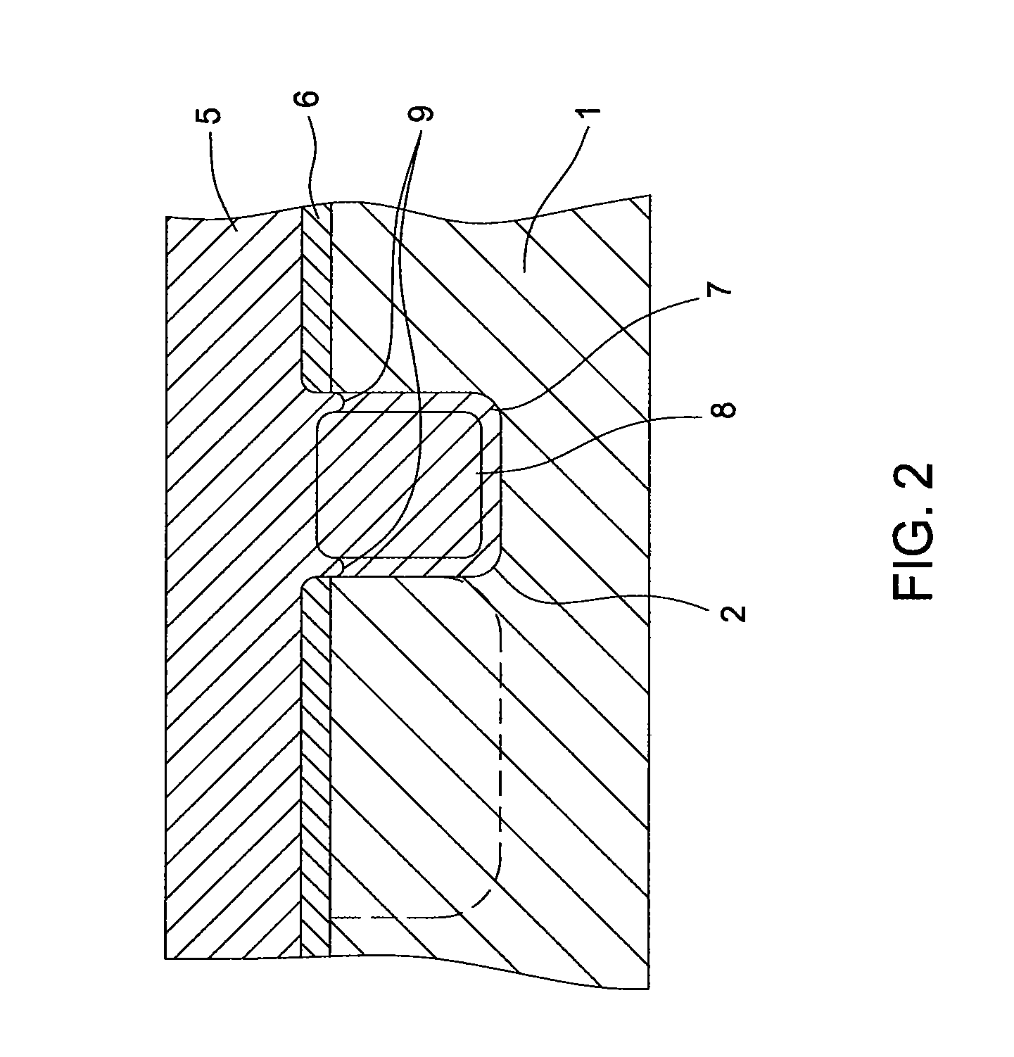
Image

Examples
examples
[0079]Substrates were exposed to various etching processes to remove native oxide layers and to form passivated surfaces thereon. Subsequently, the substrates were exposed to ambient conditions during a queue time and a secondary native oxide layer formed on the passivated surfaces. The thickness of these secondary native oxide layers were monitored with respect to the queue time while being exposed to ambient conditions, as graphically illustrated in FIG. 6. The various etching processes included Experiments A-E, as summarized in the chart below.
[0080]
NH3NF3NH3 / NF3Plasmaflow rateflow ratemolarpowerSubstrate(sccm)(sccm)ratio(W)A————B7014530C10050230D10052030E10052015
[0081]In Experiment A, Substrate A was exposed to a HF wet clean solution and process. Substrates B and C, in Experiments B and C, were exposed to a mixture of etching gases having a NH3 / NF3 molar ratio of about 5 and about 2, respectively, and were both exposed to a plasma ignited with a RF power of about 30 watts. Subs...
PUM
| Property | Measurement | Unit |
|---|---|---|
| temperature | aaaaa | aaaaa |
| molar ratio | aaaaa | aaaaa |
| pressure | aaaaa | aaaaa |
Abstract
Description
Claims
Application Information