Cutting tool
a cutting tool and tool body technology, applied in the field of cutting tools, can solve the problems of insufficient cutting performance, shortening the life of the turning machine, and insufficient wear resistance and fracture resistance, and achieves excellent oxidation resistance, high wear resistance, and high fracture resistance.
- Summary
- Abstract
- Description
- Claims
- Application Information
AI Technical Summary
Benefits of technology
Problems solved by technology
Method used
Image
Examples
first embodiment
[0032]In a cutting tool (hereinafter referred to simply as “tool”) of the present invention, a cross ridge between a rake face and a flank is shaped like a cutting edge, and a coating layer is formed on the surface of a substrate.
[0033]In accordance with the present invention, the coating layer has a composition of Ti1−a−b−c−dAlaWbSicMd(CxN1−x), where M is at least one selected from Nb, Mo, Ta, Hf and Y, 0.45≦a≦0.55, 0.01≦b≦0.1, 0.01≦c≦0.05, 0.01≦d≦0.1, and 0≦x≦1. In this composition region, oxidation start temperature can be raised to improve oxidation resistance and wear resistance. Further, chipping that is likely to occur at the ridge of the cutting edge can be suppressed to increase fracture resistance.
[0034]When “a” (Al content) is smaller than 0.45, the oxidation resistance of the coating layer may be lowered. When “a” is larger than 0.55, there is a tendency that the crystal structure of the coating layer is changed from cubic crystal to hexagonal crystal, and hardness is lo...
second embodiment
[0050]In a second preferred embodiment of present invention, a substrate is composed of cemented carbide where a tungsten carbide phase is bound by a 5 to 7 mass % of a binder phase. The tungsten carbide phase has two peak tops in the particle size distribution, namely a peak top on the side of fine particles having a particle size of 0.1 to 0.8 μm, and a peak top on the side of coarse particles having a particle size of 1.5 to 3.0 μm.
[0051]The tool provided with the cemented carbide of the construction mentioned above has high wear resistance and high fracture resistance. Specifically, when the peak top position on the fine particle side is 0.1 μm or more, the toughness of the substrate becomes high, and hence the fracture resistance of the tool is not lowered. When the peak top position on the fine particle side is 0.8 μm or less, the hardness of the substrate is high, and hence the wear resistance of the tool is improved. On the other hand, when the peak top position on the coars...
third embodiment
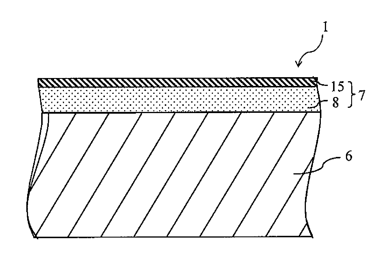
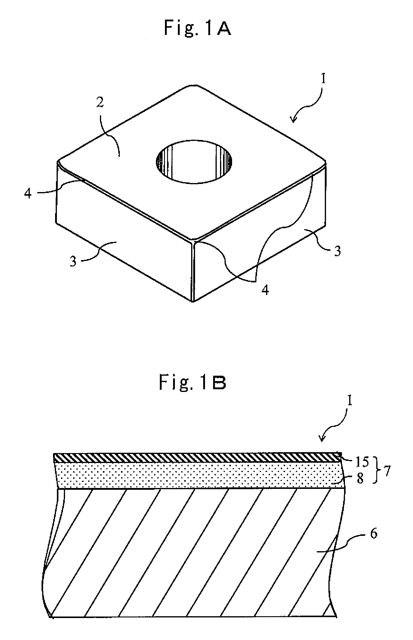
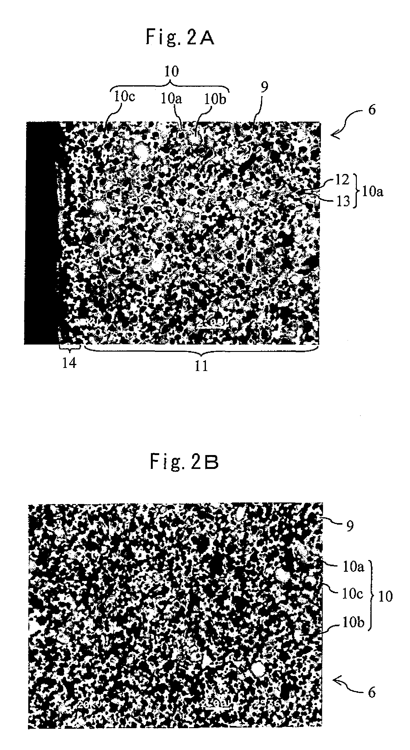
[0061]A cutting tool of a third preferred embodiment will be described with reference to the schematic perspective view in FIG. 1A, the schematic sectional view in FIG. 1B, and the scanning electron micrographs in the vicinity of the surface and the inside of the cutting tool shown in FIGS. 2A and 2B, respectively.
[0062]As shown in FIG. 1A, in the cutting tool 1 of the third preferred embodiment, a cross ridge between a rake face 2 and a flank 3 is shaped like a cutting edge 4, and as shown in FIG. 1B, a coating layer 7 is formed on the surface of a substrate 6. The substrate 6 is composed of cermet.
[0063]That is, the substrate 6 is made up of a binder phase 9 composed of an iron family metal such as Co or Ni, and a hard phase 10 composed of carbon nitride of metals of the groups 4, 5 and 6 of the periodic table, in which Ti and W are used as essential components, and Ti is contained in the largest amount. The hard phase 10 has a mean particle diameter din of 0.1 to 1.5 μm. There ex...
PUM
| Property | Measurement | Unit |
|---|---|---|
| particle size | aaaaa | aaaaa |
| particle size | aaaaa | aaaaa |
| mean particle diameter | aaaaa | aaaaa |
Abstract
Description
Claims
Application Information
 - R&D
- Intellectual Property
- Life Sciences
- Materials
- Tech Scout
- Unparalleled Data Quality
- Higher Quality Content
- 60% Fewer Hallucinations
Browse by: Latest US Patents, China's latest patents, Technical Efficacy Thesaurus, Application Domain, Technology Topic, Popular Technical Reports.
© 2025 PatSnap. All rights reserved.Legal|Privacy policy|Modern Slavery Act Transparency Statement|Sitemap|About US| Contact US: help@patsnap.com


