Remotely reconfigurable system for mapping subsurface geological anomalies

a remote reconfigurable system and geological anomaly technology, applied in the direction of digital computer details, instruments, nuclear elements, etc., can solve the problems of subsurface anomalies, subsurface anomalies, subsurface anomalies, etc., to achieve more accurate calculation of resistivity models, increase the accuracy of sensors, and avoid excessive downtime and expensive field repairs

Active Publication Date: 2010-10-12
EARTHSYST TEHNOLOGIES INC +1
View PDF20 Cites 10 Cited by
  • Summary
  • Abstract
  • Description
  • Claims
  • Application Information

AI Technical Summary

Benefits of technology

[0029]In one aspect of the invention, the sensor associated with each electrode includes a wireless transmitter and receiver. The wireless transmitter and receiver eliminate the need for individual leads that connect each data connection device to the control processor. The wireless transmitter and receiver further eliminate the need for pre-fabricated cable assemblies that are permanently connected between the sensors and to the electrodes. In one aspect of the invention, the sensors are connected to the electrodes and are further inter-connected to one another with a current source by a common extension cord through standard type connections.
[0032]In an alternative aspect of the invention, each sensor includes a Global Positioning System (GPS) receiver that provides the control processor with a spatial location for the sensor and a correlation between that sensor and its spatial location. The invention further provides the advantage of automatic location of the sensors by GPS signals. Further, the GPS location of the sensors provides increased accuracy in location of the sensors which allows for more accurate calculation of the resistivity model.
[0033]In the event of damage to a sensor or damage to an interconnecting cable, a replacement sensor or cable may be added to the array of sensors without excessive downtime and expensive field repairs because all of the sensors are identical and the cables are standard 3-conductor extension cords. The replacement sensor can unambiguously identify itself and its spatial relationship with respect to other sensors to the control processor for use by the mapping software.
[0034]The use of wireless communications further eliminates the use of complex control cabling and the substantial voltage losses and inaccuracies associated with them.

Problems solved by technology

Concrete is very strong in compression, usually rated up to 2,500 PSI, but it is relatively weak in tension.
Slab on grade foundations are prone to cracking due to deflection when the subgrade sinks or becomes unstable due to moisture.
Detecting and locating fluid leaks and other subsurface anomalies beneath composite concrete and asphalt structures is often a difficult and destructive task.
Methods of the prior art often require destruction of large sections of the composite structures to locate leaks and other subsurface anomalies because the exact location of the leak or anomaly is unknown.
However, reinforced concrete drastically attenuates radar signals such that an accurate return signal is fusually (??) unobtainable.
Moreover, radar is not well suited to detecting small leaks, nor for differentiating between small leaks and variations in soil composition or the presence of roots and other anomalies.
However, Daily does not allow the electrodes to be placed directly under an existing structure.
However, Henderson '045 does not disclose a method of directly monitoring the subgrade beneath a structure without permanently burying the electrodes or a method to place electrodes beneath an existing structure.
First, it requires an electrically conductive fluid container.
Second, it requires that the electrodes be permanently buried in the soil surrounding the tank.
Also, it requires the use of an AC generator, which is less convenient than a DC power source.
However, Bryant does not disclose the ability to switch current between nodes or to conduct an orderly permutation of voltage measurements between nodes.
None of the prior art is entirely satisfactory to locate fluid leaks beneath composite and reinforced concrete and asphalt structures or to analyze them in near real time.
For instance, it is not practical to electrify the potentially leaking fluid and because there may exist multiple sources of fluid, mise-a-la-masse is not a practical option.
Nor is it practical to embed permanently a series of electrodes beneath an existing massive concrete structure or roadway to monitor soil resistivity.
Further, because some of the ERT methods use multiple-plate electrodes where a large hole is bored to insert the electrodes into the subjacent soil making the method impractical and destructive.
In addition, placing the electrodes around the periphery of a roadbed or foundation is less accurate compared to placing the electrodes directly beneath or adjacent the potential leak source.
However, Sheard does not provide a method of distributing current to various nodes for systematically reading all the permutations of voltages provided pursuant to the distributed current to provide a complete and reliable data set.
Also, Sheard does not provide a method to address each node dynamically so that the nodes are truly interchangeable.
However, Longaker does not provide for multiple positions of injection current or the controlled monitoring of a permutation of voltages between nodes.
Also, Longaker does not provide for dynamically addressable sensors to allow for easy interchangeability.
The current state of the art is unsatisfactory because it does not provide a method to remotely change injection current locations or to conduct an orderly progression through a permutation of voltages and currents between nodes.
Moreover, the state of the art does not provide for dynamically addressable sensors whose location and address can be changed on demand.
Furthermore, the present state of the art requires that the electrodes be placed in a linear, regularly spaced grid pattern that does not provide needed flexibility in the physical layout of arrays of electrodes in multiple, non-linear arrangements.
However, situations arise where it is necessary to arrange the electrodes in a non-linear grid if the physical layout of the concrete or underlying area to be measured prevents the layout of electrodes in a typical, linear grid arrangement.
Furthermore, the prior art does not provide for a means to easily adjust an array of electrodes to avoid encapsulated steel structures such as rebar.
The requirement of physically measuring and placing electrodes is hampered by structures which include buildings, medians, or other obstructions which makes placing the electrodes accurately difficult.
The inaccurate placement of electrodes leads to errors in the mathematical calculations required to analyze the locations of the anomalies and therefore reduces the overall efficiency and accuracy of the system.
The present state of the art is further unsatisfactory because the sensors are affixed to the interconnecting cables and to the electrodes at predetermined intervals.
A sensor or a part of the interconnecting cable or an electrode may become damaged or cease to function and require replacement.
Physical damage to or failure of a given sensor within a long strand of conducting cable requires replacement of the sensor or substitution of a conducting cable, frequently associated with a substantial downtime for repair or replacement.
In order to repair a part of the interconnecting cable, sensor and electrode combination, it may be necessary to remove the entire section of cable with a plurality of sensors and electrodes from service and effect expensive and time-consuming repairs.
Moreover, the state of the art does not provide for interchangeability of sensors.
This limitation requires extensive time in setting up a grid and replacing defective sensors.
The voltage loses in such cabling are substantial and require corrective and potentially inaccurate algorithms in the analytical software used to generate the subterranean mapping.
A need further exists for a non-unique sensor attached to the electrodes which is addressable and reconfigurable so that expensive and time consuming cable and sensor unit replacement is unnecessary.

Method used


Image

  • Remotely reconfigurable system for mapping subsurface geological anomalies
  • Remotely reconfigurable system for mapping subsurface geological anomalies
  • Remotely reconfigurable system for mapping subsurface geological anomalies

Examples


first embodiment

[0099]The way in which addresses are determined for each voltage control unit is dependent on the embodiment chosen of the current invention. In a first embodiment, known as the “thumbwheel” method shown in FIG. 8, thumbwheels 634 are used to set an address number between 000 and 999 manually on each voltage control unit. In this case, the master controller is supplied internally with a table that maps known addresses between 000 and 999 to physical locations of electrodes in the array.

[0100]In a similar method, known as the “IR (infrared)” method, IR port 636 on the voltage control units are used to communicate an address to controller 604 via communications card 602. The IR port receives the address via a handheld PDA programmed to uniquely assign addresses to the voltage control units, according to a table. The identical table is used by the master controller to mathematically correlate the data received from each voltage control unit with its physical location. In an alternate e...

second embodiment

[0101]In a second embodiment, known as the “first-to-wake” method, the order of deployment of the voltage control units is used to set the addresses of each. In this embodiment, the first voltage control unit to “wake up” or come on line is addressed by the master control unit who assigns an address to it. Since the addresses are assigned in a physical order, the master controller is aware of the spatial relationship of the voltage control units. In most applications the interstitial distance between the electrodes is the same, or nearly the same. In this embodiment, once the electrodes are deployed then the voltage control units are deployed, one per electrode. The voltage control units are deployed in order starting from a first proximal position and proceeding linearly along the line of deployment of the electrodes to the most distal electrode position. After each voltage control unit is attached to its electrode, it is activated through switch 1303. In this method, the voltage c...

third embodiment

[0102]In a third embodiment, known as the “GPS location method”, the voltage control units determine their longitude and latitude location provided by the GPS card as they are switched on. This longitude and latitude location is then uploaded to the master controller along with a unique address stored in the memory of each voltage control unit. The addresses are correlated with physical locations by the master controller and used to coordinate the functions of the voltage control units and measurements returned from them. Moving to step 1411, if necessary, the master control program uploads position data from each of the voltage control units.

[0103]Entering a loop at step 1413, the master controller calculates switch settings to determine a “switch mask”. A switch mask is then uploaded to each of the voltage control units at step 1415. Two examples of switch masks are shown at FIG. 15.

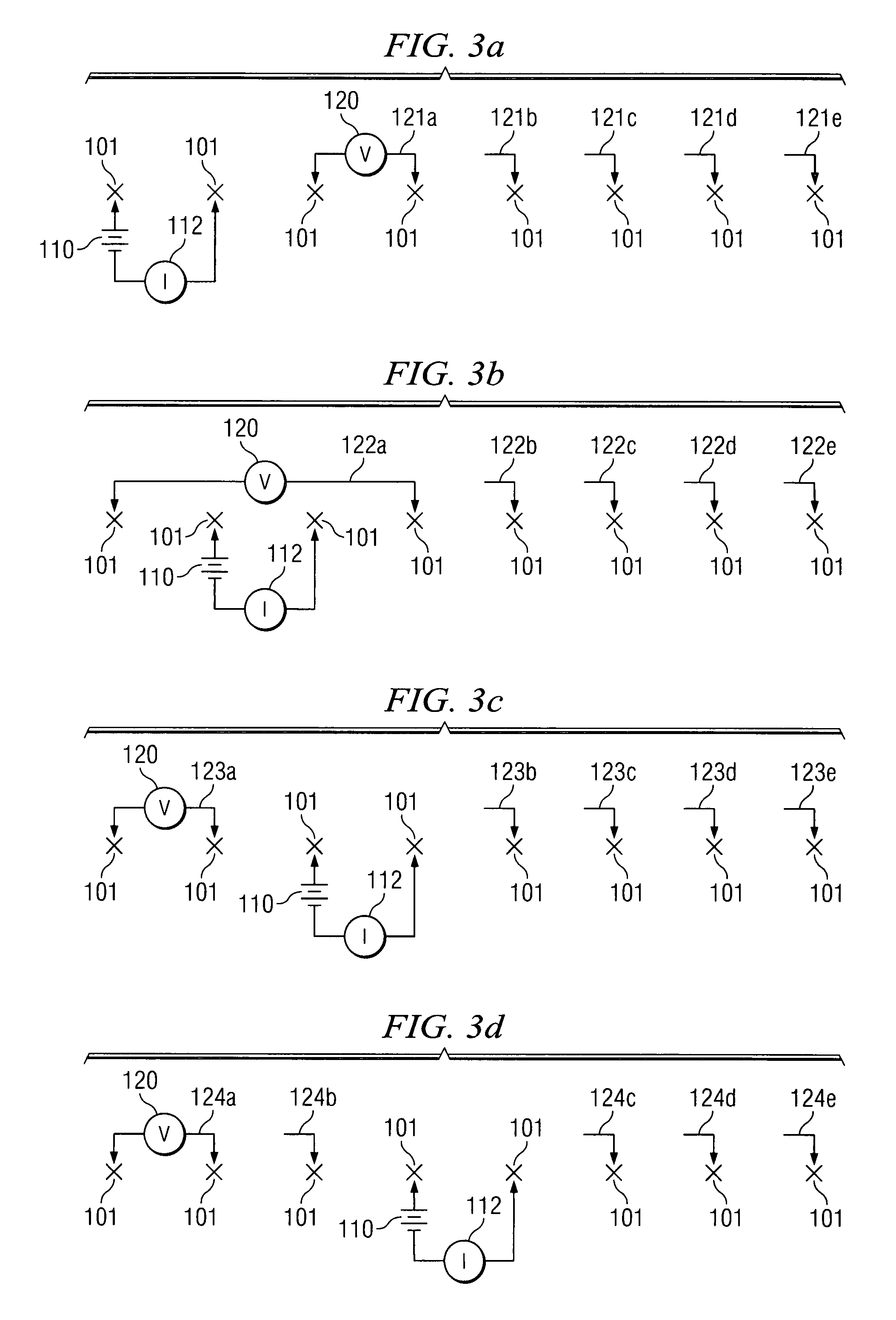
[0104]Referring then to FIG. 15 and FIG. 3a, a switch mask for position 121a for each voltage contr...


PUM


Abstract

Methods and apparatus are provided for receiving, detecting and transmitting geophysical data from a plurality of electrodes inserted through a structure's pavement foundation in a non-destructive manner and into the soil utilizing a dynamically reconfigurable wireless control unit located on each electrode. Data from the control units is transmitted by a wireless signal to a centralized data processor for analysis. Control data is provided from a central control processor to the control unit by wireless transmission. The control unit, which is positioned, includes a multi-channel radio frequency transmitter / receiver and a processor to actuate relays and record data returns from the measured substrate soil for transmission to the central data processor. The control unit incorporates a changeable code or address to unambiguously identify itself, and its spatial relationship to other electrodes, to the central data processor and the central control processor. The control units are equipped with a GPS positioning device to allow for automatic transmission of electrode location and for electrode placement without a manual survey being required.

Description

CROSS-REFERENCE TO RELATED APPLICATIONS[0001]This application is a Continuation-In-Part claiming priority benefit from U.S. patent application Ser. No. 11 / 472,901 which was filed on Jun. 22, 2006, now U.S. Pat. No. 7,386,402 issued on Jun. 10, 2008.TECHNICAL FIELD OF THE INVENTION[0002]This invention relates to a method for producing a subsurface electrical resistivity model. More specifically, this invention relates to a method for resistivity modeling for locating anomalies, such as groundwater, leaks, tree roots, and other vegetation, particularly beneath and around roadbeds. Raw resistivity data is collected by a reconfigurable wireless network of sensors that distributes current and measures voltage. A regression correlation is performed on the raw resistivity data to create a resistivity model, which is converted to graphical form, then analyzed to detect and locate subsurface soil anomalies. A three dimensional “movie” is then prepared to analyze the anomalies in near real ti...

Claims


Application Information

Patent Timeline
Patent Type & Authority Patents(United States)
IPC IPC(8): G01R3/00
CPCG01V1/22G01V3/02
Inventor BRYANT, JOHN
Owner EARTHSYST TEHNOLOGIES INC
Why Eureka
Try Eureka