
Transparent film for display substrate, display substrate using the film and method of manufacturing the same, liquid crystal display, organic electroluminescence display, and touch panel

a technology of transparent film and substrate, which is applied in the direction of identification means, thin material handling, instruments, etc., can solve the problems of plasticizer reducing and high expansion coefficient of cellulose ester, so as to reduce the glass-transition temperature of cellulose ester, increase the thermal expansion coefficient, and high moisture absorbing expansion coefficient

Active Publication Date: 2010-10-26
KONICA MINOLTA INC
View PDF17 Cites 3 Cited by
  • Summary
  • Abstract
  • Description
  • Claims
  • Application Information

AI Technical Summary

Benefits of technology

[0015]However, cellulose ester is a moisture absorbing resin and has a disadvantage of having a high moisture absorbing expansion coefficient. To make up for this defect of the cellulose ester, as much as 5 through 20 percent by mass of such a plasticizer as a phosphoric acid ester is used in the prior art. However, it has been found out that the plasticizer reduces the glass-transition temperature of the cellulose ester and increases the thermal expansion coefficient.
[0016]In an effort to solve the aforementioned problems, the inventors of the present invention have found out that a high glass-transition temperature can be achieved by keeping the percentage of plasticizer content down below a predetermined level, and at the same time, the thermal expansion coefficient can be reduced by biaxially drawing of the cellulose ester film. Further, surprisingly, it has been found out that cellulose ester is excellent controllability of birefringence; the birefringence can be kept small even if the cellulose ester is drawn. The disadvantage of reduced amount of the plasticizer to be added can be reduced by formation of a gas barrier. These findings have led to the present invention.

Problems solved by technology

However, cellulose ester is a moisture absorbing resin and has a disadvantage of having a high moisture absorbing expansion coefficient.
However, it has been found out that the plasticizer reduces the glass-transition temperature of the cellulose ester and increases the thermal expansion coefficient.

Method used


Image

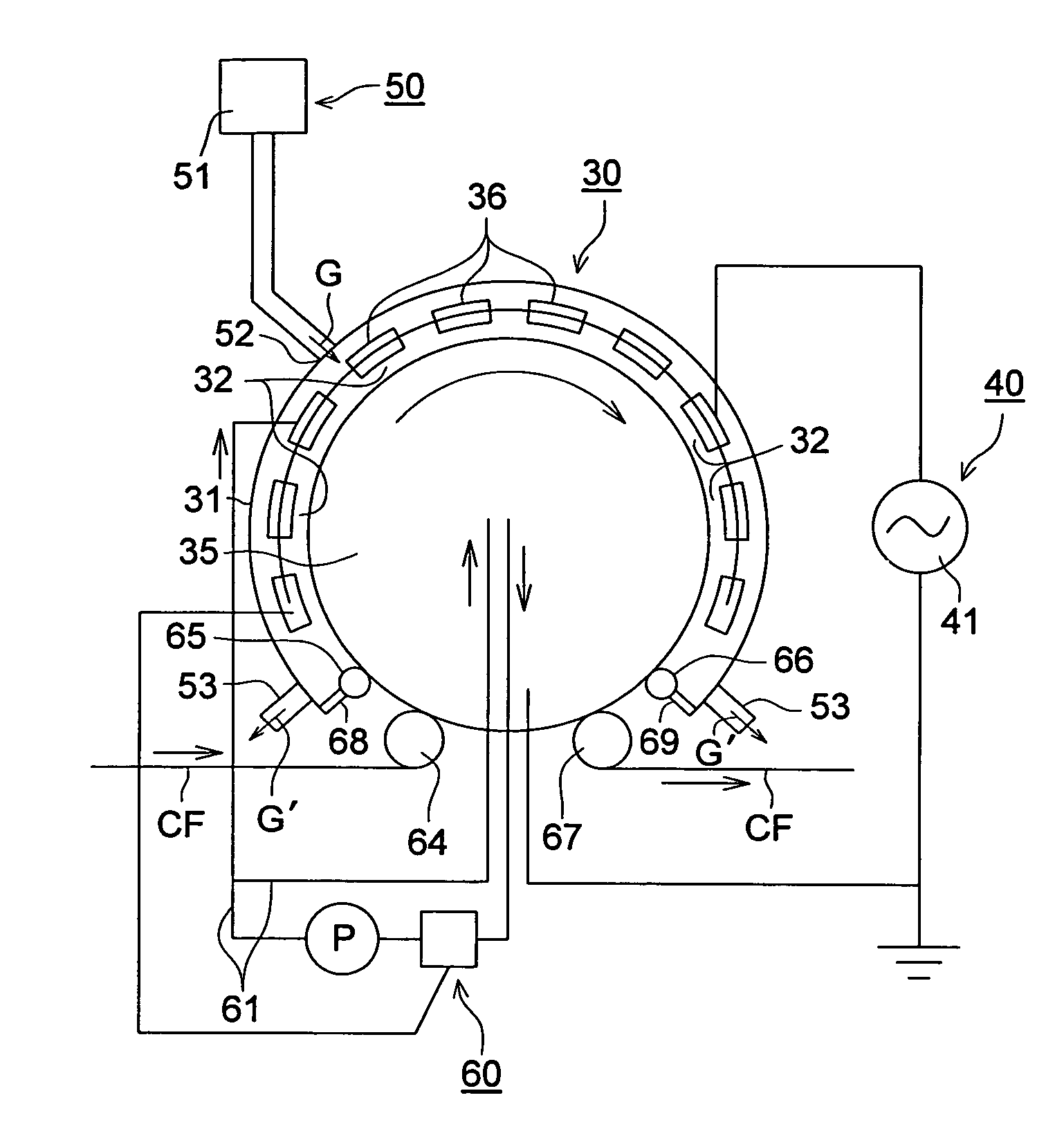
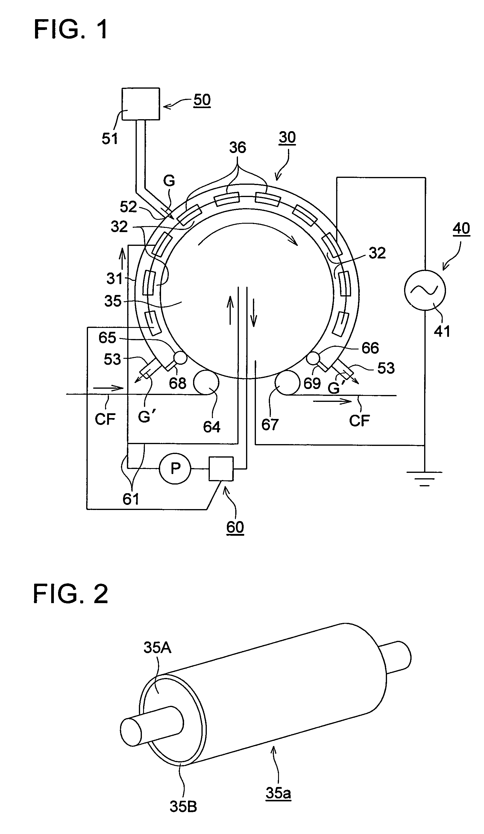
  • Transparent film for display substrate, display substrate using the film and method of manufacturing the same, liquid crystal display, organic electroluminescence display, and touch panel
  • Transparent film for display substrate, display substrate using the film and method of manufacturing the same, liquid crystal display, organic electroluminescence display, and touch panel
  • Transparent film for display substrate, display substrate using the film and method of manufacturing the same, liquid crystal display, organic electroluminescence display, and touch panel

Examples


embodiment 1

[0332]

[0333]Synthesis was carried out by reference to the synthesis method disclosed in the J. Appl. Polym. Sci., vol. 58, 1263-1274(1995).

[0334]100 parts by mass of diacetyl cellulose (hereinafter referred to as “DAC”) was dissolved in 700 parts by mass of dehydrated tetrahydrofuran (hereinafter referred to as “THF”). After that, 10 parts by mass of 3-isocyanatepropylethoxysilane (hereinafter referred to as “IPTES”) was dropped, and 0.8 parts by mass of dibutyl tin dilaurate was dropped as a catalyst. This was stirred under heating and reflex for five hours.

[0335]Five hours later, the infrared absorption spectrum of the solution was measured. It was revealed that the absorption of 2271 cm−1 derived from the isocyanate group of the IPTES had been disappeared. Accordingly, heating was suspended and the solution was left to cool down. It was poured into 3 L of methanol to be settled again, whereby a white solid was obtained at a yield of 99.6%. The Si29−NMR spectrum of the white solid...

embodiment 2

[0416]Transparent conductive films 201 through 223 were prepared by forming thin films on the substrate films 101 through 123 obtained in the first embodiment in the order of the clear hard coated layer (on both surfaces), moisture proof film (on both surfaces) and transparent conductive film (on one surface).

[0417]

[0418]The substrate film 101 was coated using an extrusion coater so that the composition of the coating of the following hard coated layer would have a film thickness of 3 μm. After that, it was dried for one minute by the drier with its temperature set at 80 degrees Celsius, and was then exposed to ultraviolet irradiation of 120 mW / cm2, whereby the clear hard coated layer was formed.

[0419]

(Coating composition of clear hard coated layer)Dipenta-erithritol hexaacrylate monomer:60parts by massDipenta-erithritol hexaacrylate dimmer:20parts by massDipenta-erithritol hexaacrylate trimer:20parts by massDimethoxybenzophenone:4parts by massEthyl acetate:50parts by massMethylethy...

embodiment 3

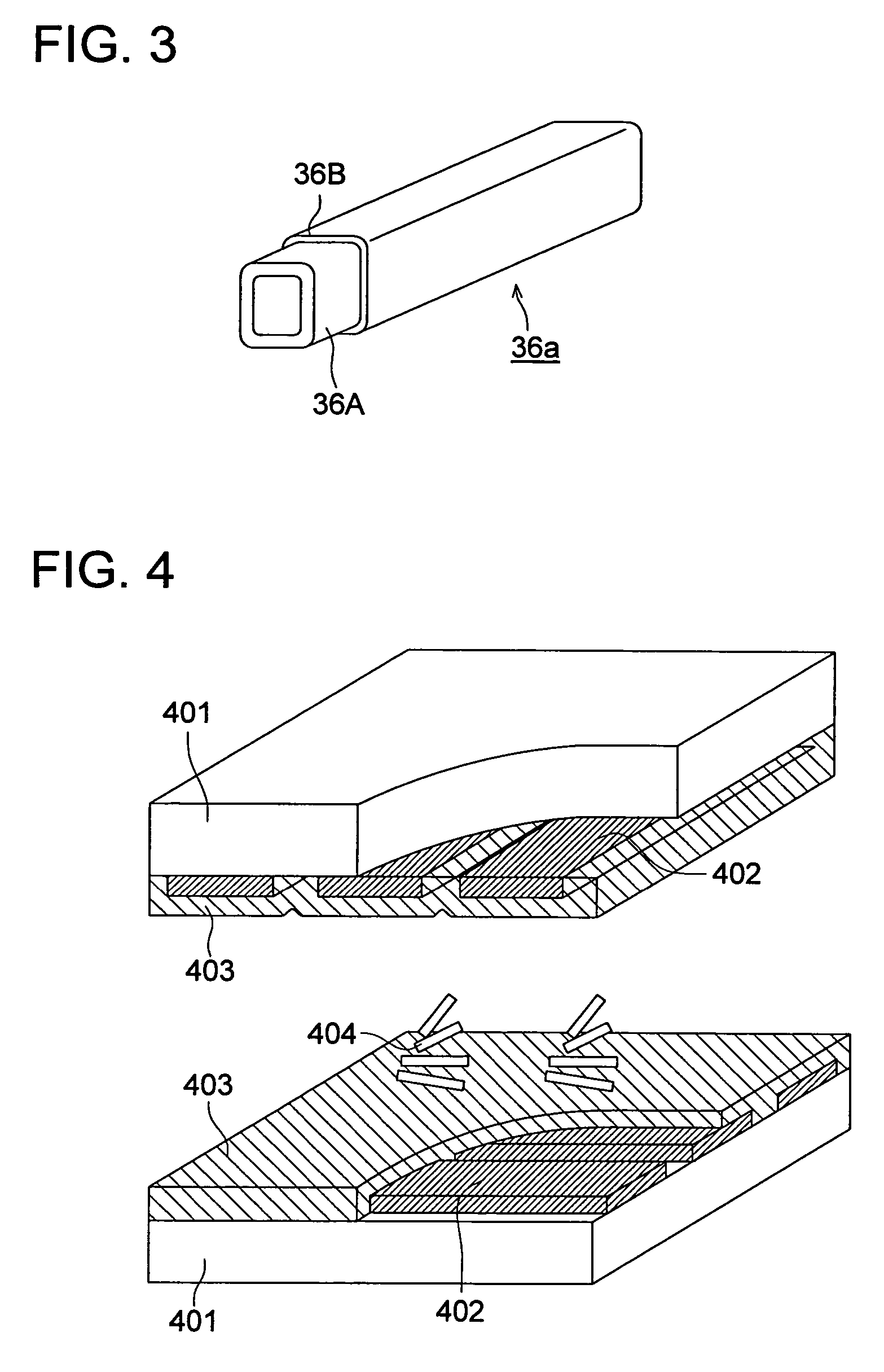
[0443]A TN liquid crystal display device given in FIG. 4 was manufactured according to the following procedure, using the aforementioned transparent conductive films 201 through 205 and 207 through 218 of the present invention, and the transparent conductive films 206 and 219 through 223 of comparative examples.

[0444]

[0445]A resin layer (not illustrated) for smoothing was coated on the aforementioned transparent conductive film as a transparent conductive substrate 401. A transparent conductive film was formed further on this resin layer directly or via a silicon dioxide film. This was provided with patterning to form a stripe-like shape, so that a display electrode 402 was formed. An opposing substrate was produced using the same transparent conductive substrate. Namely, a display electrode was formed on the opposing substrate side as well. Further, an oriented film 403 and sealing material (not illustrated) were formed by a printing method or the like. Two substrates were placed o...


PUM

PropertyMeasurementUnit
transparentaaaaaaaaaa
glass-transition temperatureaaaaaaaaaa
wavelengthaaaaaaaaaa

Abstract

A transparent film for display substrate containing a cellulose ester, a plasticizer content in an amount of less than 1 percent, the aforementioned film being drawn 3 through 100 percent both in the direction of conveyance and across the width.

Description

FIELD OF THE INVENTION[0001]The present invention relates to a transparent film for display substrate characterized by a low coefficient of linear expansion and preferable application to a display substrate, and the manufacturing method thereof, particularly to a liquid crystal display, organic electroluminescence display and touch panel wherein this transparent film for display substrate is used as a substrate.TECHNICAL BACKGROUND[0002]Since glass has an excellent thermal stability and transparency as well as low vapor permeability, the glass have been used in the prior art as a substrate for the electronic display device such as a liquid crystal display device, organic electroluminescence (EL) display device, plasma display device and electronic paper, as a substrate for an electron-optical device such as a CCD or CMOS sensor, or a substrate for a solar battery. However, with the recent spread of a cellular phone and portable information terminal, there is an active demand for a s...

Claims


Application Information

Patent Timeline
Patent Type & Authority Patents(United States)
IPC IPC(8): B32B7/02G02F1/1333G09F9/30
CPCG02F1/1333G09F9/30Y10T428/10Y10T428/1055Y10T428/1086C09K2323/04C09K2323/06C09K2323/00
Inventor OKUBO, YASUSHIKIYOHARA, KAZUTOKAWABE, SATOMI
Owner KONICA MINOLTA INC
Learn More