
Method to reduce wastewater treatment plant footprints and costs

a wastewater treatment plant and footprint technology, applied in water/sewage multi-stage treatment, biological water/sewage treatment, water/sewage treatment by oxidation, etc., can solve the problems of unsuitable material for any beneficial use, difficult to reduce the content of treated wastewater brine, and unsuitable for industrial discharge sludge or biosolids, etc., to reduce sulfur dioxide and reduce the amount of treatment plant footprint

Inactive Publication Date: 2011-01-11
EARTH RENAISSANCE TECH
View PDF9 Cites 13 Cited by
  • Summary
  • Abstract
  • Description
  • Claims
  • Application Information

AI Technical Summary

Benefits of technology

"The present invention is a method and apparatus for reducing the footprint of wastewater treatment plants using sulfur dioxide chemical dewatering and disinfection technology. The method involves supersaturating the wastewater with sulfur dioxide to quickly condition and separate the solids from the liquid fraction. The excess sulfur dioxide is then removed and reused, reducing the amount of lime and overall costs of operation. The conditioning process results in a color change and odor replacement, making the wastewater safe for disposal. The invention can be used as a primary treatment process for domestic sewage, industrial wastewater, and agricultural waste."

Problems solved by technology

Tertiary or advanced treatment does not reduce the treated wastewater brine content, requiring energy intensive Quaternary brine treatment removal using reverse osmosis and distillation, and other methods.
The presence of contaminants in the sludge or bio-solids arising from industrial discharges is a more challenging problem and may be the deciding factor in determining the choice of a utilization disposal option.
The contaminants accumulate in the biomass and sludge, and can render the material unfit for any beneficial use.
Primary and secondary sludge generally contain no more than four percent solids, and the storage and transportation costs of this semi-liquid material limit the application to nearby farmland.
This gelatinous mechanically separated mass is then usually land filled or admixed with other fuels for burning, and may contain significant pathogens and heavy metals.
If these separated solids are treated with chlorine for pathogen kill, chlorinated carcinogens often result, creating a different environmental hazard.
If treated with chlorine to kill pathogens before land application or dumping, its usage for agricultural purposes is less than ideal as any residual chlorine acts as an herbicide.
This long dwell time results in further concentrations of the brines.
Other mechanical filtration methods provide sludge separation, but require continual unplugging of the filters; generating significant ongoing costs of filter replacement and declining effectiveness as the filter becomes plugged with the separated solids.
However, it is a technique requiring significant upfront capital investment, a large dewatering footprint, and may result in long term environmental clean-up and remediation costs.
As urban populations being served grow and landfill costs increase, these plants seldom meet permitting constraints without significant upgrades in design, particularly with respect to pathogen gray water discharge and the negative impacts caused by mountains of gelatinous solids.
These chemical wastewater treatment methods are not package systems, not moveable as needed to accommodate the needs of a community, particularly in riparian areas subject to flooding, rely heavily on the use of polymers, and they do not address the issues of BOD's and ammonia in treated wastewater or brine disposal methods.
This smaller footprint design then requires large amounts of lime or other chemicals for pH adjustment to neutralize excess sulfur dioxide; thereby increasing operating costs.
Alternatively, lower concentrations of sulfur dioxide can be used with larger tanks to provide longer dwell times, thus increasing the treatment plant's capital costs and footprint, but lowering the amount of lime or other chemicals for pH adjustment and sulfur dioxide neutralization.

Method used


Image

  • Method to reduce wastewater treatment plant footprints and costs
  • Method to reduce wastewater treatment plant footprints and costs
  • Method to reduce wastewater treatment plant footprints and costs

Examples


Embodiment Construction

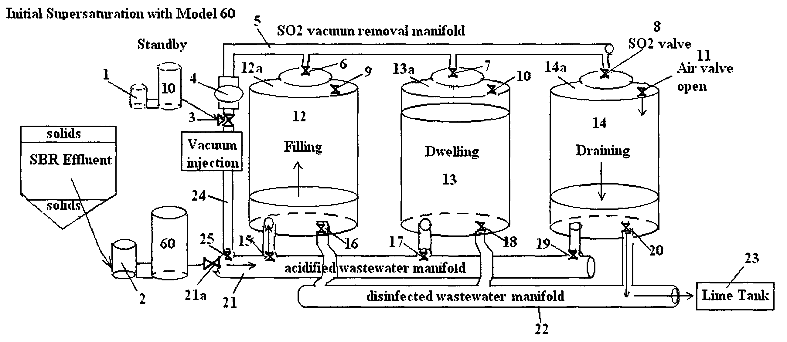
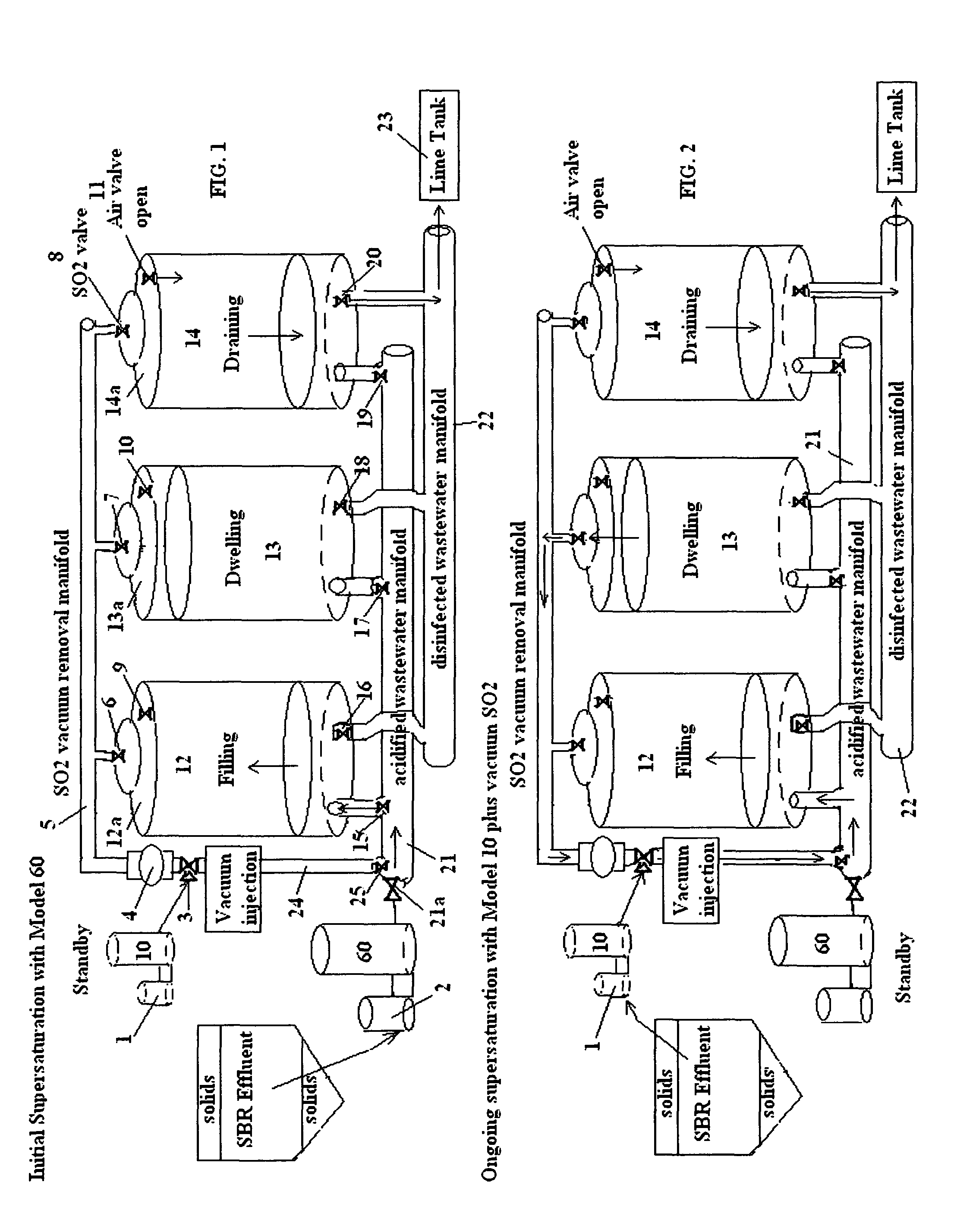
[0081]FIG. 1 illustrates a typical dual sulfur generator layout of a rapid chemical dewatering method in an initial super saturation mode. Two sulfurous acid generators 1, 2 are associated as part of a circuit to alternatively treat effluent from a sequential batch reactor (SBR). The larger is a Model 60 Harmon Systems International sulfurous acid generator 2 capable of treating ½ MGD burning 75 pounds sulfur / hour, which first is used to supersaturate the SBR effluent, which enters an acidified wastewater manifold 21 controlled by a valve 21a, which then sequentially fills three enclosed 20,000 gallon treatment tanks, 12, 13, 14. The three tanks 12, 13, 14 are sequentially filled within a short distance from their enclosed tops 12a, 13a, 14a, leaving an air space wherein excess sulfur dioxide gas accumulates and is concentrated. These tank tops 12a, 13a, 14a have air valves 9, 10, and 11 and SO2 removal valves 6, 7, 8. The air valves 9, 10, 11 are in communication with the atmospher...


PUM

PropertyMeasurementUnit
pHaaaaaaaaaa
pressureaaaaaaaaaa
mean retention timeaaaaaaaaaa

Abstract

A method and apparatus for reducing the footprint of chemical / mechanical / biological wastewater treatment facilities employing sulfur dioxide disinfection and chemical dewatering of solids in conjunction with an environmental biological systems for treating the separated treated wastewater.

Description

RELATED APPLICATIONS[0001]This application is a continuation-in-part of prior application Ser. No. 12 / 456,387 filed Jun. 16, 2009 entitled “Wastewater Treatment Apparatus, which is a continuation-in-part of prior application Ser. No. 11 / 438,247 filed May 22, 2006 now U.S. Pat. No. 7,563,372 entitled “Package Dewatering Wastewater Treatment Method, and claims the benefit of U.S. Provisional Application No. 60 / 684,392, filed May 25, 2005.BACKGROUND OF THE INVENTION[0002]1. Field[0003]This invention comprises a method and apparatus to reduce the wastewater treatment plant footprint of facilities employing rapid sludge chemical dewatering technology to produce a disinfected treated recovered wastewater.[0004]2. State of the Art[0005]Various sewage treatment methods and plants are known. Most large municipal systems employ a series of settling ponds sequentially concentrating the solids contained in wastewater either with or without polymers for separation from liquids via mechanical sep...

Claims


Application Information

Patent Timeline
Patent Type & Authority Patents(United States)
IPC IPC(8): C02F3/00C02F11/147
CPCC02F9/00C02F1/56C02F1/66C02F11/14C02F2101/20C02F2201/008C02F2303/04C02F11/147
Inventor HARMON, JOHNTHEODORE, MARCUS G.WARDLE, LARRY P.
Owner EARTH RENAISSANCE TECH
Learn More