Nanowires in thin-film silicon solar cells

a technology of solar cells and nanowires, which is applied in the direction of nanotechnology, semiconductor devices, electrical equipment, etc., can solve the problems of limiting the conversion efficiency of a standard cell to about 44%, and none is efficient enough to drive down the cost involved in the production and use of this technology

Inactive Publication Date: 2011-02-22
GENERAL ELECTRIC CO
View PDF11 Cites 16 Cited by
  • Summary
  • Abstract
  • Description
  • Claims
  • Application Information

AI Technical Summary

Benefits of technology

[0009]In some embodiments, the present invention is directed to photovoltaic (PV) devices comprising elongated silicon (Si) nanostructures (e.g., nanowires, nanorods, etc.) as active PV elements, wherein such devices are typically thin film Si solar cells. Generally, such solar cells are of the p-i-n type. Additionally, the present invention is also directed at methods of making and using such devices, and to systems and modules (e.g., solar panels) employing such devices. In some such embodiments, the elongated nanostructures enhance the performance of conventional thin film solar cells by increasing the charge collection due to the nanoscale proximity to the film for charge separation. In some such embodiments, the light is primarily absorbed within the thin film materials, rather than within the nanostructures, and the cell is typically designed such that a substantial fraction of the light is absorbed within the intrinsic layer of the thin film cell.

Problems solved by technology

Single and multi-junction p-n solar cells are used for this purpose, but none are efficient enough to drive down the costs involved in the production and use of this technology.
Consequently, competition from conventional sources of electricity precludes the widespread use of such solar cell technology.
This loss alone limits the conversion efficiency of a standard cell to about 44%.
Additionally, recombination of photo-generated electrons and holes with trap states in the semiconductor crystal associated with point defects (interstitial impurities), metal clusters, line defects (dislocations), planar defects (stacking faults), and / or grain boundaries reduces the efficiency further.
Although this latter reduction in efficiency can be overcome by using other materials with appropriate properties, particularly long diffusion lengths of the photo-generated carriers, this still does not bring this technology to a cost parity with more conventional sources of electricity.
Further loss is incurred owing to the fact that semiconductors will not absorb light with energy lower than the bandgap of the material used.
The primary issue with thin film solar cells based on amorphous silicon is that the mobility of the charge carriers is very low—particularly that of the holes.
Such hole-mobility is the limiting factor for amorphous silicon thin film solar cells.
While the intrinsic layer of such solar cells can be made thinner, which increases the chance for the holes to reach the front of the cell, there is significant loss of absorption.
To overcome this loss, tandem and triple junctions may be employed, but this is significantly more complex.
Such arrays, however, were not configured for use in photovoltaic devices, nor was it suggested how such arrays might serve to increase the efficiency of solar cells.
However, such nanowires are not active photovoltaic (PV) elements; they merely serve in an anti-reflective capacity.

Method used


Image

  • Nanowires in thin-film silicon solar cells
  • Nanowires in thin-film silicon solar cells
  • Nanowires in thin-film silicon solar cells

Examples


example 1

[0069]This Example serves to illustrate formation of a conformal layer of amorphous Si on crystalline Si nanowires (formed by an wet etching process), in accordance with some embodiments of the present invention.

[0070]A silicon wafer is bonded to a piece of metal foil or a metallized glass wafer using standard metallurgical bonding methods. The wafer is then thinned to a desired thickness in a standard Si etchant such as a mixture of hydrofluoric, acetic, and nitric acids. Once the desired thickness is reached, typically being 5 μm to 20 μm, the nanowires (representative elongated nanostructures) are formed in the silicon by immersion in a silver nitrate / hydrofluoric acid solution. The conformal i-n junction is formed by plasma-enhanced chemical vapor deposition (PECVD), followed by deposition of a top transparent conducting oxide (TCO). A via is established for backside contact and final top and bottom contacts are formed by a shadow mask deposition process. FIGS. 6 and 7 are scann...

example 2

[0071]This Example serves to illustrate formation of a conformal layer of amorphous Si on CVD-grown crystalline Si nanowires, in accordance with some embodiments of the present invention.

[0072]Silicon nanowires are grown on a conductive substrate material such as stainless steel foil, or a doped ZnO-coated glass wafer, after deposition of a suitable catalyst thin film or nanoparticle layer. In one such embodiment, a nanoporous template layer is first established on top of the back contact material by anodization and then a catalyst is placed within the pores of the template electrochemically. Once the nanowires are grown, the conformal i-n junction is formed by plasma-enhanced chemical vapor deposition (PE-CVD), followed by deposition of a top transparent conducting oxide (TCO). An example of a thick amorphous silicon layer deposited on CVD-grown Si nanowires is shown in FIGS. 8 and 9. FIGS. 8 and 9 are scanning electron microscopy images of conformal amorphous Si layer on a Si nano...

example 3

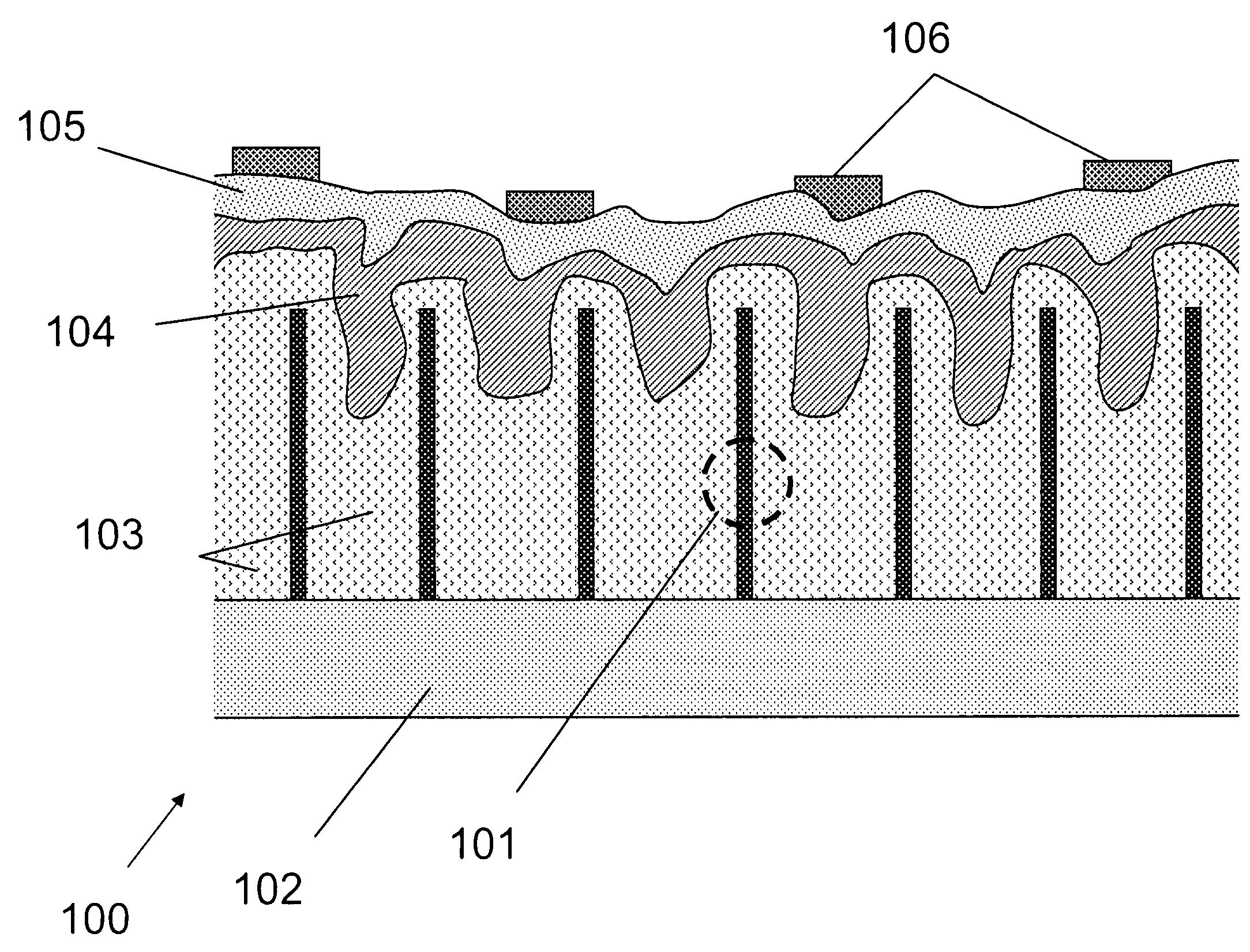
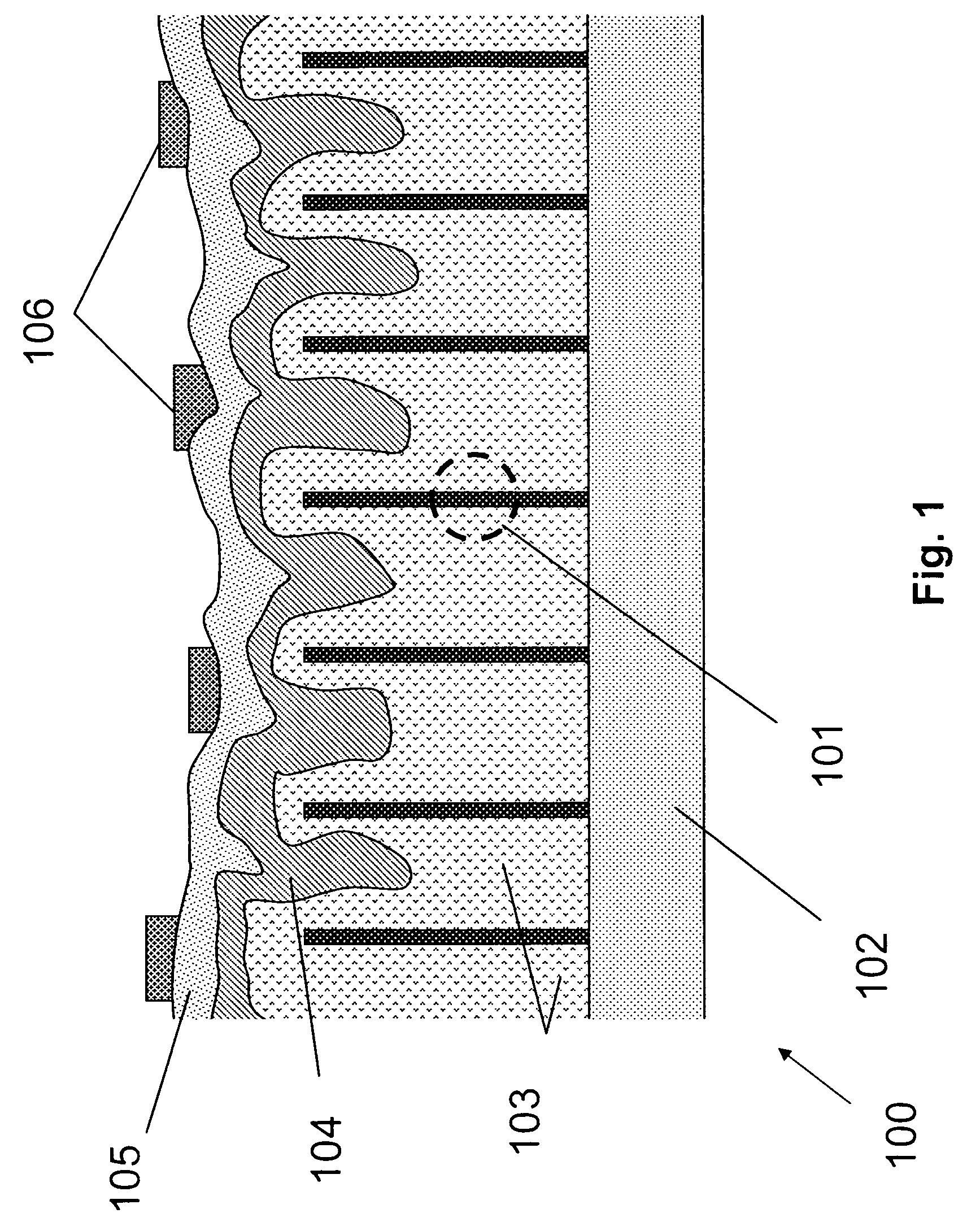
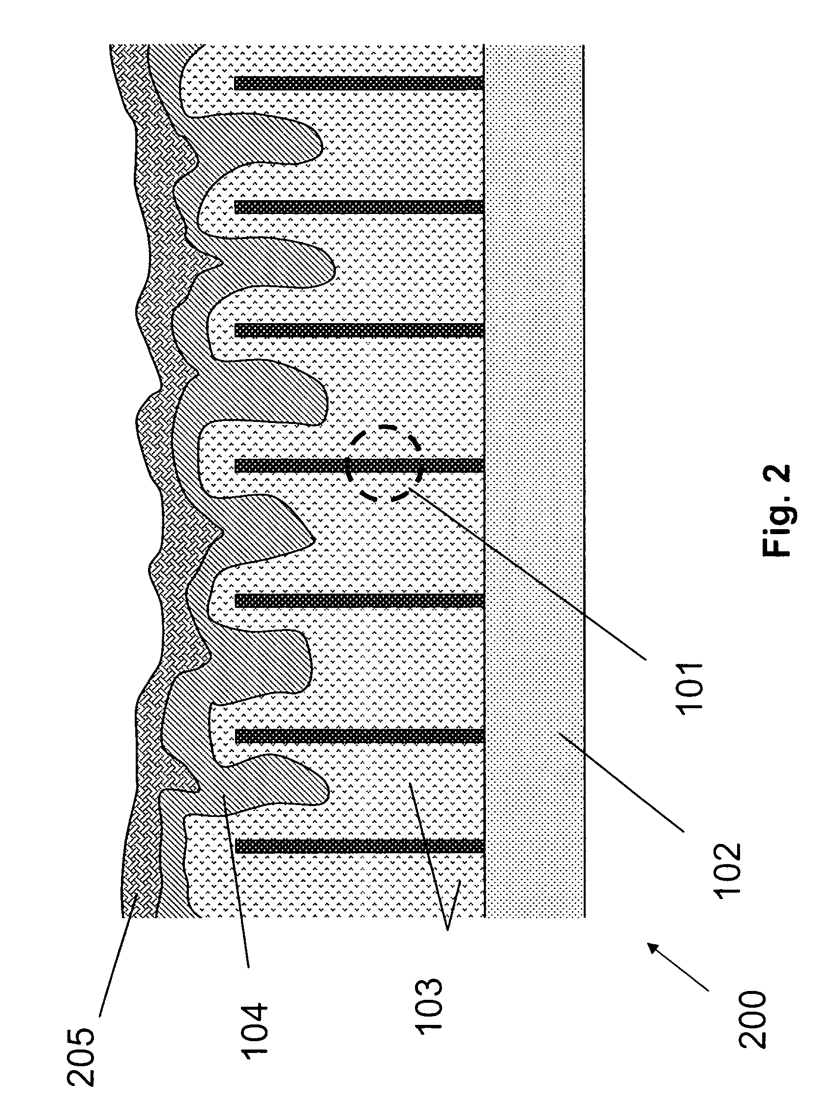
[0073]This Example serves to illustrate an exemplary system comprising photovoltaic devices 100, in accordance with some embodiments of the present invention.

[0074]The photovoltaic device(s) 100 and / or 200 can be packaged in a photovoltaic module such that they are physically isolated from the environment. The module front surface is made of glass to allow sunlight to penetrate, and electrical leads are established on the backside for incorporation into a PV power system. In one embodiment, the photovoltaic device 100 / 200 is grown on a large glass substrate with an intermediate doped ZnO layer such that the glass substrate becomes the protecting glass for the PV module, the original growth layer for the nanowires now being the “front contact” (in terms of the direction in which it is illuminated). Corresponding “backside contact” is then established at the original top surface of the elongated nanostructure layer.


PUM


Abstract

In some embodiments, the present invention is directed to photovoltaic (PV) devices comprising silicon (Si) nanowires as active PV elements, wherein such devices are typically thin film Si solar cells. Generally, such solar cells are of the p-i-n type and can be fabricated for front and / or backside (i.e., top and / or bottom) illumination. Additionally, the present invention is also directed at methods of making and using such devices, and to systems and modules (e.g., solar panels) employing such devices.

Description

TECHNICAL FIELD[0001]The present invention relates generally to thin-film photovoltaic devices, and specifically to such photovoltaic devices comprising elongated silicon nanostructures as active elements within the device.BACKGROUND INFORMATION[0002]Presently, silicon (Si) is the most commonly used material in the fabrication of solar cells, such solar cells being used for converting sunlight into electricity. Single and multi-junction p-n solar cells are used for this purpose, but none are efficient enough to drive down the costs involved in the production and use of this technology. Consequently, competition from conventional sources of electricity precludes the widespread use of such solar cell technology.[0003]The primary loss process in existing solar cells occurs when a photo-excited electron quickly loses any energy it may have in excess of the bandgap due to interactions with lattice vibrations, known as phonons, resulting in increased recombination. This loss alone limits ...

Claims


Application Information

Patent Timeline
Patent Type & Authority Patents(United States)
IPC IPC(8): H01L31/00H01L31/075
CPCB82Y20/00H01L31/035245H01L31/035254H01L31/03529H01L31/075Y10S977/72Y10S977/762Y10S977/948Y10S977/954Y10S977/712Y02E10/548
Inventor KOREVAAR, BASTIAAN ARIETSAKALAKOS, LOUCAS
Owner GENERAL ELECTRIC CO
Why Eureka
Try Eureka