Thermal spray formation of polymer compositions

a polymer composition and thermal spray technology, applied in the direction of electrostatic spraying apparatus, tribo-charging spraying, coating, etc., can solve the problems of inability to incorporate thermal spray technology, high cost of manual methods involving cutting foam components from large bungs, and high cost of manual methods. , to achieve the effect of facilitating thermal spraying of difficult-to-spray materials, reducing or eliminating thermal degradation of materials, and economic application of polymer foams and coating

Active Publication Date: 2011-06-14
FARRAR LAWRENCE C +2
View PDF32 Cites 22 Cited by
  • Summary
  • Abstract
  • Description
  • Claims
  • Application Information

AI Technical Summary

Benefits of technology

[0039]One advantage of the invention is that economical application of polymer foams and coatings is possible. Another advantage of the invention is that volatile organic carbon (VOC) releases are not necessary. Yet another advantage of the invention is that thermal degradation of the material is reduced or eliminated. A further advantage of the invention is to facilitate thermal spraying of difficult-to-spray materials, such as polyamides.
[0040]The invention provides a method and system for applying polymer compositions to substrates and the foams and coatings so applied. Polymer compositions that can be applied with the invention include thermoplastic and thermoset polymers (only one of a very wide range of materials demonstrated with this technology, including polyamides, polyetherimides, polyimides, polyesters, epoxies, silicones, and liquid crystal polymers), foams, coatings, syntactic foams, materials with blowing agents, materials with binders, and electrostatic sprays. Metallized materials may be added to the polymer compositions for reduction of electromagnetic interference, stealth and fire protection. Both open cell foams and closed cell foams may be applied with the invention.
[0041]In another preferred embodiment, the invention is a method for directly applying a high temperature polymer as foam onto a substrate using a field deployable system. Preferably, the invention involves spraying polymer micro-balloons to form an adherent, mechanically-sound, low-density, high-quality insulating foam. The invention preferably involves using both radiation and convection to process the polymer materials while spray forming the foam.
[0042]In another preferred embodiment, the invention is a fully contained, field deployable apparatus that includes power distribution, heater controls, foam constituent material bins, flow controls, material transportation functions and a thermal spray apparatus. Operation of this embodiment requires only a power source, plant air and

Problems solved by technology

These methods do not incorporate thermal spray technology (e.g., use of high temperatures to process constituent materials into a desired form while spraying onto a substrate).
Related art methods and systems for applying polymer foams and coatings have serious limitations.
Manual methods which involve cutting foam components from large bungs are very expensive.
Solvent spray methods release toxic (volatile organic compounds, VOC's) to the environment.
Related art thermal spray methods which relay on hot combustion gas (3,000° C.) or hot plasma gas (10,000° C.) can result in overheating of spray particles in flight, which can cause degradation of the sprayed material, and in coatings that are rough, porous and poorly bonded.
These limitations are particularly acute when the polymer being sprayed is a thermoplastic polyamide, such as nylon, or a composition that comprises a polyamide.
In fact, because of the potential for thermal degradation of the material, no operable polyamide spray foaming processes have been developed.
The foregoing review of t

Method used


Image

  • Thermal spray formation of polymer compositions
  • Thermal spray formation of polymer compositions
  • Thermal spray formation of polymer compositions

Examples


Embodiment Construction

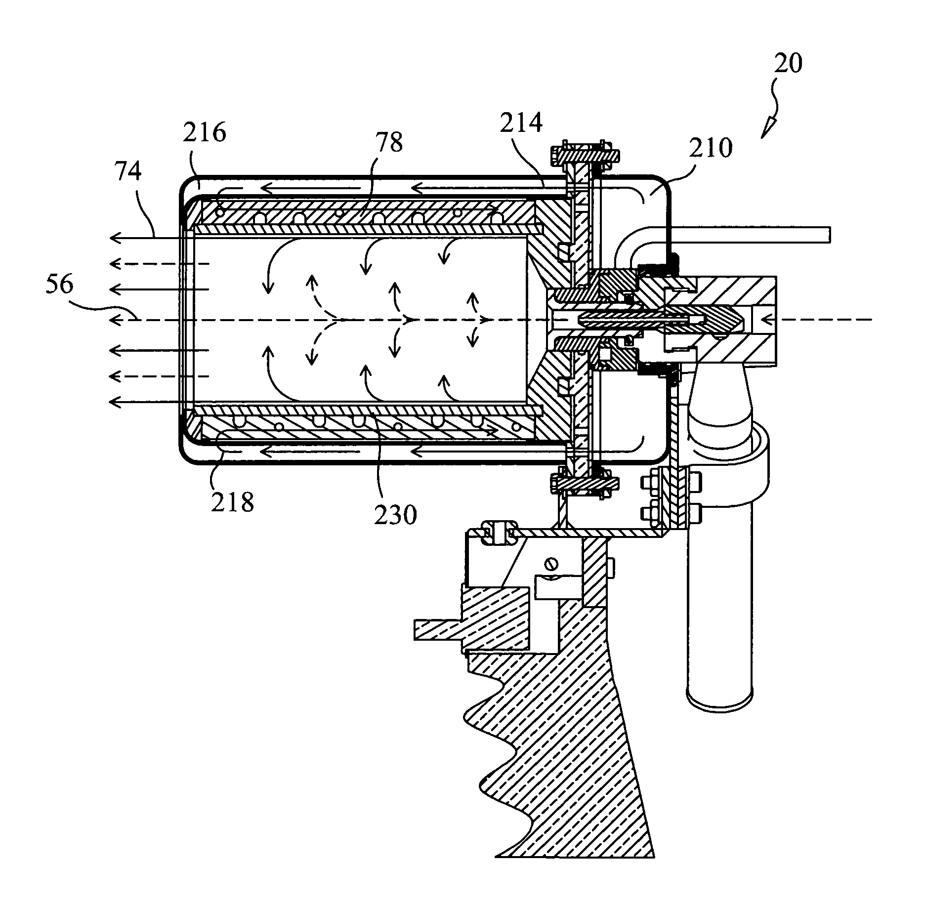
[0169]Referring to FIG. 1, a preferred embodiment of system 10 is illustrated. In this embodiment, system 10 is a self-contained, field-deployable thermal spray system. System 10 comprises five distinct yet integrated operating segments: on-board power distribution segment 12, control panel segment 14, powder bin segment 16, umbilical hose segment 18 and spray gun segment 20. In a preferred embodiment, segments 12, 14 and 16 are incorporated into cart 19.

[0170]When supplied with 480-volt single-phase power, power distribution segment 12 utilizes transformers to provide 240-volt, 120-volt AC power as well as 24-volt DC power to the rest of system 10. Control panel segment 14 provides the operator of system 10 control of the power to the various heaters, temperature control of the various heaters, flow control of the carrier gas, selection of the type of carrier gas used, as well as on / off control of the vibrator attached to the powder bin segment 16. Insulated, heated umbilical hose ...


PUM

PropertyMeasurementUnit
Temperatureaaaaaaaaaa
Compositionaaaaaaaaaa
Electric chargeaaaaaaaaaa

Abstract

A system and method for applying a material, such as a polymer composition, to a substrate, the method comprising mixing the material with a heated carrier gas stream, spraying the material through a nozzle, and radiant and convective heating of the material during transport. Preferred embodiments of the system and method can be used to spray polyetherimides, polyimides, polyamides, thermoset resins (e.g., and epoxies, polyesters and silicones), liquid crystal polymers, compositions comprising a blowing agent, compositions comprising a binder, compositions comprising a metallized material, compositions that produce an open cell foam, and compositions that produce a closed cell foam.

Description

CROSS-REFERENCE TO RELATED APPLICATIONS[0001]This application claims the benefit of U.S. Provisional Application No. 60 / 513,304, filed Oct. 21, 2003, the disclosure of which application is incorporated by reference as if fully set forth herein.STATEMENT REGARDING FEDERALLY SPONSORED RESEARCH OR DEVELOPMENT[0002]The U.S. Government has a paid-up license in this invention and the right in limited circumstances to require the patent owner to license others on reasonable terms as provided for by the terms of (Contract No. NAS1-00069) awarded by the National Aeronautics and Space Administration.BACKGROUND OF THE INVENTION[0003]This invention relates to a system and method for radiative spraying of polymeric compositions. In particular, the invention relates to a system and method for radiant thermal spray application of polymer foams and other coatings.[0004]A variety of technologies are used to apply polymeric foams and coatings to substrates in the aerospace, aircraft, marine, automoti...

Claims


Application Information

Patent Timeline
IPC IPC(8): B05D1/02
CPCB05B5/032B05B7/1486B05B7/1606B29C44/3415B05D1/02C08J9/32B29C70/66B05B5/047B05B7/162B05D3/02B05B15/0431B05B12/18
Inventor FARRAR, LAWRENCE C.COOK, AARON M.COGUILL, SCOTT L.
Owner FARRAR LAWRENCE C
Why Eureka
Try Eureka