

Material for organic electroluminescent device, organic electroluminescent device, and organic electroluminescent display
a technology of electroluminescent devices and materials, applied in the direction of luminescent compositions, thermoelectric devices, organic chemistry, etc., can solve the problems of shortening the life of the resultant device, increasing the power consumption, and shortening the device life. the effect of voltag
- Summary
- Abstract
- Description
- Claims
- Application Information
AI Technical Summary
Benefits of technology
Problems solved by technology
Method used
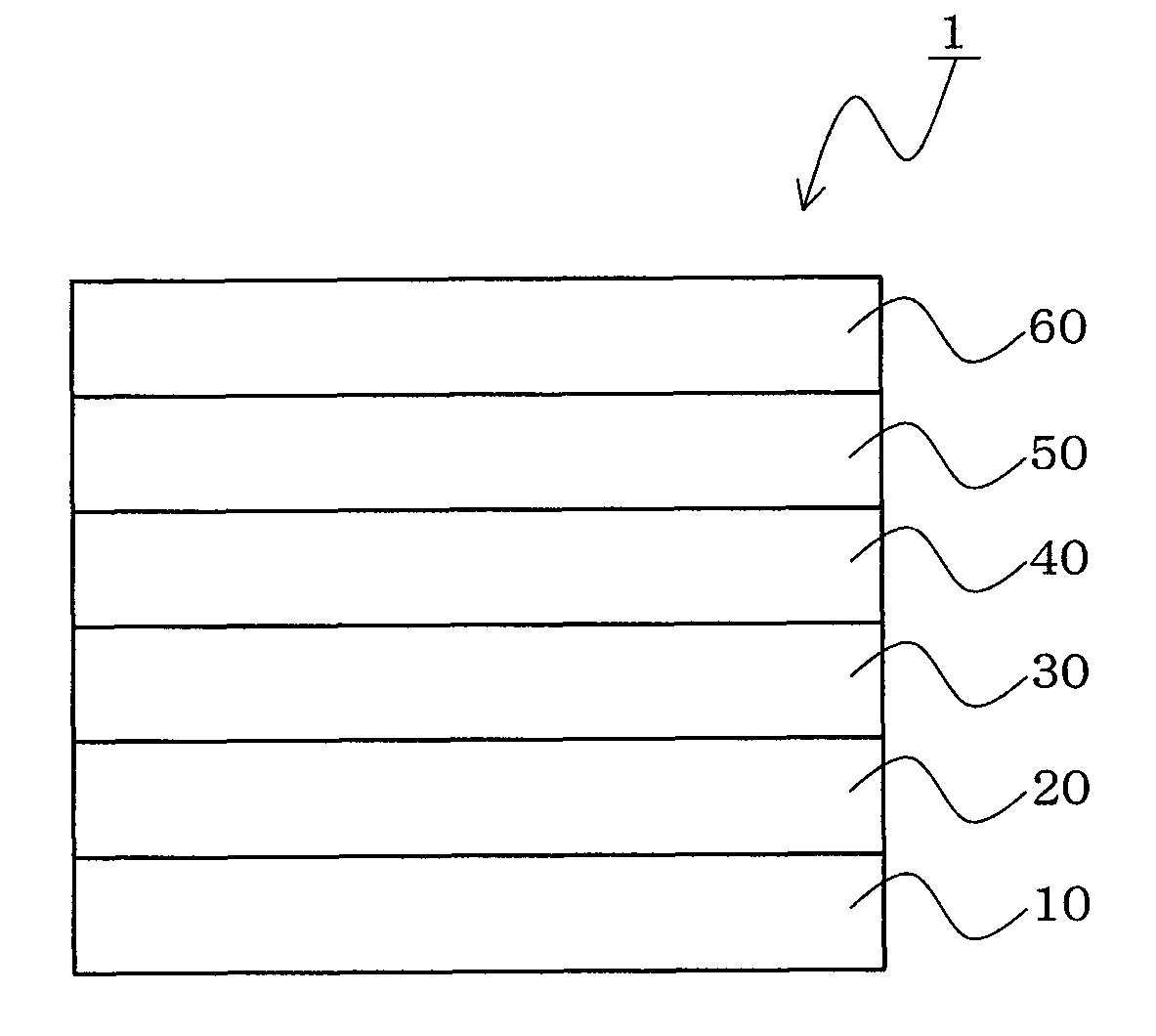
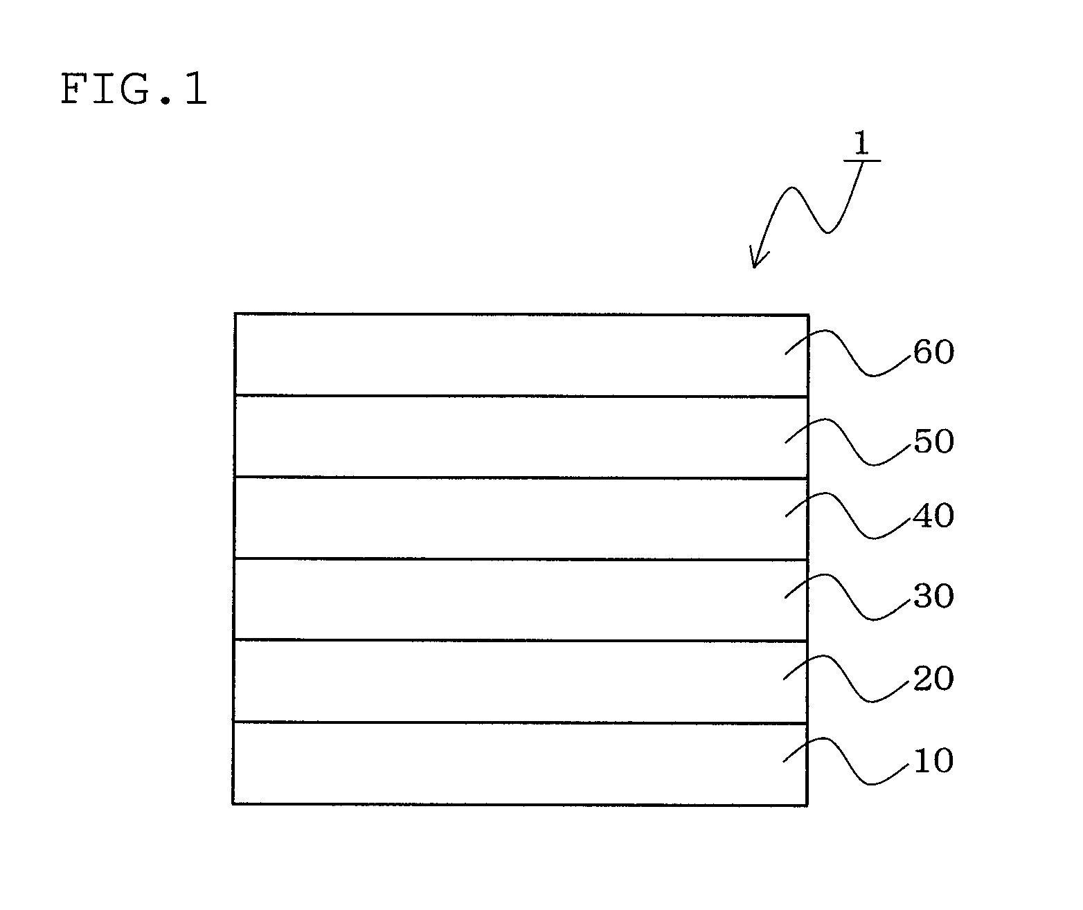
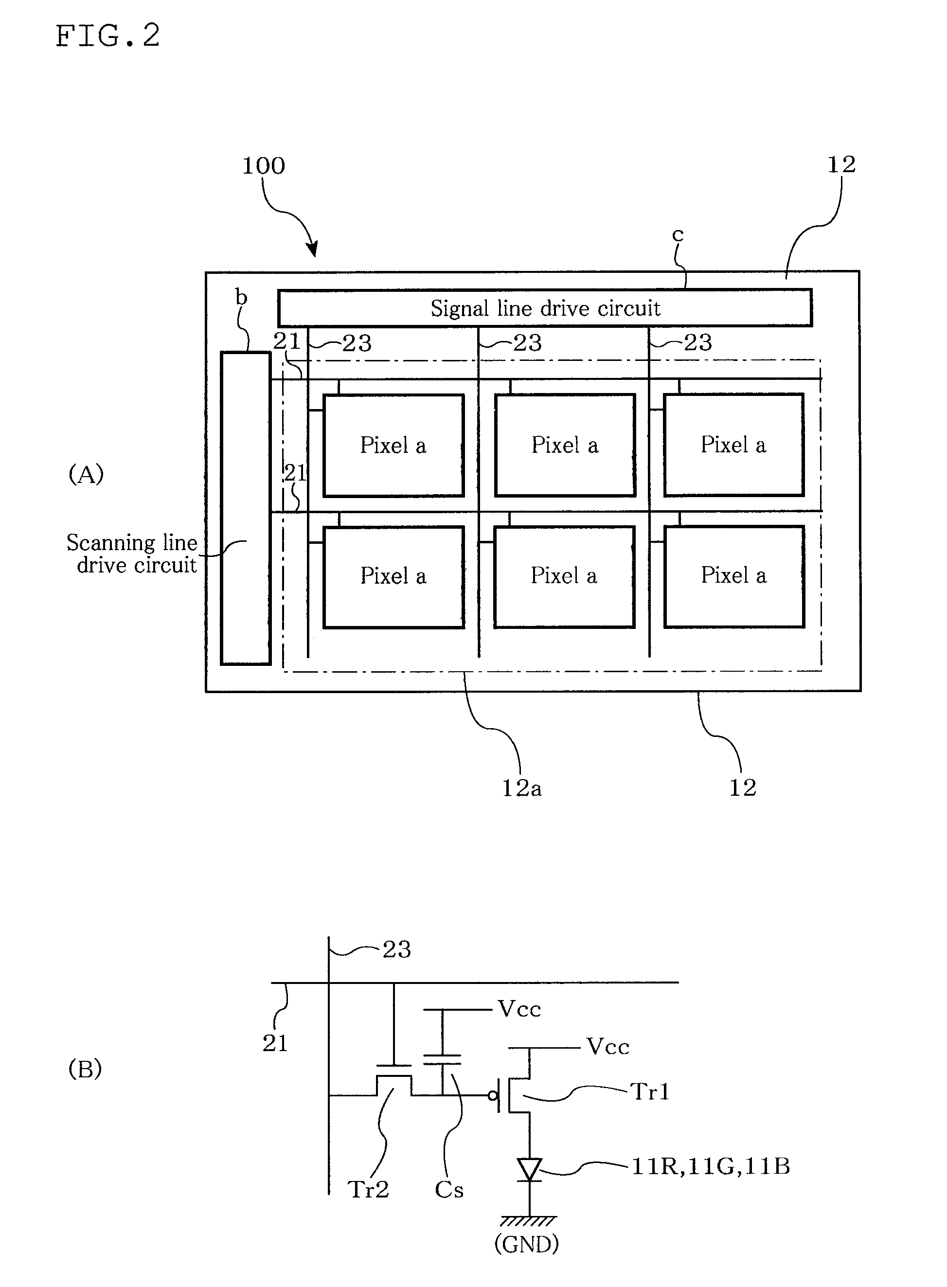
Image

Examples
example 1
Synthesis of Compound (A-3)
(1) Synthesis of Intermediate A
[0300]1.6 g of tetraminodiphenoquinone synthesized according to the method described in Justus Liebigs Ann. Chem., 667, 55 to 71 (1963), and 7.0 g of 4,4′-bis(trifluoromethyl)benzyl were added to 50 ml of acetic acid and heated at 80° C. for 3 hours with stirring. After cooling, the reaction solution was concentrated and solid precipitates were filtered and purified by a silica gel column, whereby 2.8 g of intermediate A (yellow solid) was obtained.
[0301]As a result of an IR measurement of the compound, the absorption of a carbonyl group was observed at 1705 cm−1. Mass spectrometry revealed that the compound had a peak at an M / Z of 788.
(2) Synthesis of Compound (A-3)
[0302]1.5 g of intermediate A was stirred and dissolved in 70 ml of methylene chloride. The air atmosphere in the flask was replaced with argon and the solution was cooled to −10° C. or less in a salt-ice bath. 1.4 g of titanium tetrachloride was added to the solu...
example 2
Synthesis of Compound (A-7)
(1) Synthesis of Intermediate B
[0307]Intermediate B was obtained in the same manner as the synthesis of intermediate A in Example 1, except that 7.5 g of 4,4′-difluoro-3,3′-bistrifluoromethylbenzyl was used instead of 4,4′-bistrifluoromethylbenzyl.
[0308]As a result of an IR measurement of the compound, the absorption of a carbonyl group was observed at 1705 cm−1. Mass spectrometry revealed that the compound had a peak at an M / Z of 860.
(2) Synthesis of Compound (A-7)
[0309]1.0 g of orange solid of compound (A-8) was obtained (sublimation yield: 90%) in the same manner as the synthesis of compound (A-3) in Example 1, except that 1.6 g of intermediate B was used instead of intermediate A.
[0310]As a result of an IR measurement of the compound, the absorption of a carbonyl group disappeared and the absorption of a cyano group was observed at 2155 cm−1. Mass spectrometry revealed that the compound had a peak at an M / Z of 908.
[0311]The reduction potential of the c...
example 3
Synthesis of Compound (A-8)
(1) Synthesis of Intermediate C
[0312]Intermediate C was obtained in the same manner as the synthesis of intermediate A in Example 1, except that 7.5 g of 4,4′-difluoro-3,3′-bistrifluoromethylbenzyl was used instead of 4,4′-bistrifluoromethylbenzyl.
[0313]As a result of an IR measurement of the compound, the absorption of a carbonyl group was observed at 1705 cm−1. Mass spectrometry revealed that the compound had a peak at an M / Z of 860.
(2) Synthesis of Compound (A-8)
[0314]0.6 g of orange solid of compound (A-8) was obtained (sublimation yield: 60%) in the same manner as the synthesis of compound (A-3) in Example 1, except that 1.6 g of intermediate C was used instead of intermediate A.
[0315]As a result of an IR measurement of the compound, the absorption of a carbonyl group disappeared and the absorption of a cyano group was observed at 2155 cm−1. Mass spectrometry revealed that the compound had a peak at an M / Z of 908.
[0316]The reduction potential of the c...
PUM
 Abstract
Description
Claims
Application Information