Rectenna solar energy harvester

Active Publication Date: 2012-02-14
UNIV OF SOUTH FLORIDA
View PDF13 Cites 72 Cited by
  • Summary
  • Abstract
  • Description
  • Claims
  • Application Information

AI Technical Summary

Benefits of technology

[0018]Also disclosed is a method for collecting unused electromagnetic energy. Using the device described above, unused electromagnetic radiation is absorbed in the energy absorbing material, where it is converted into thermal energy. This thermal energy is then collected by the antenna or antennas and converted by the rectenna into electricity. In some embodiments, the unused electromagnetic energy is thermal energy, ultraviolet energy, visible energy, infrared energy,

Problems solved by technology

Additionally, the cost of producing energy is skyrocketing, due in part to depleting fossil fuel reserves.
However, methods of harvesting high-frequency radiation utilizing rectennas have identified several key problems with the approach.
These problems include impedance matching, rectification, polarization, limited bandwidth and captured power.
The typical λ/2 dipole antenna only supports a single polarization a

Method used


Image

  • Rectenna solar energy harvester
  • Rectenna solar energy harvester
  • Rectenna solar energy harvester

Examples


example 1

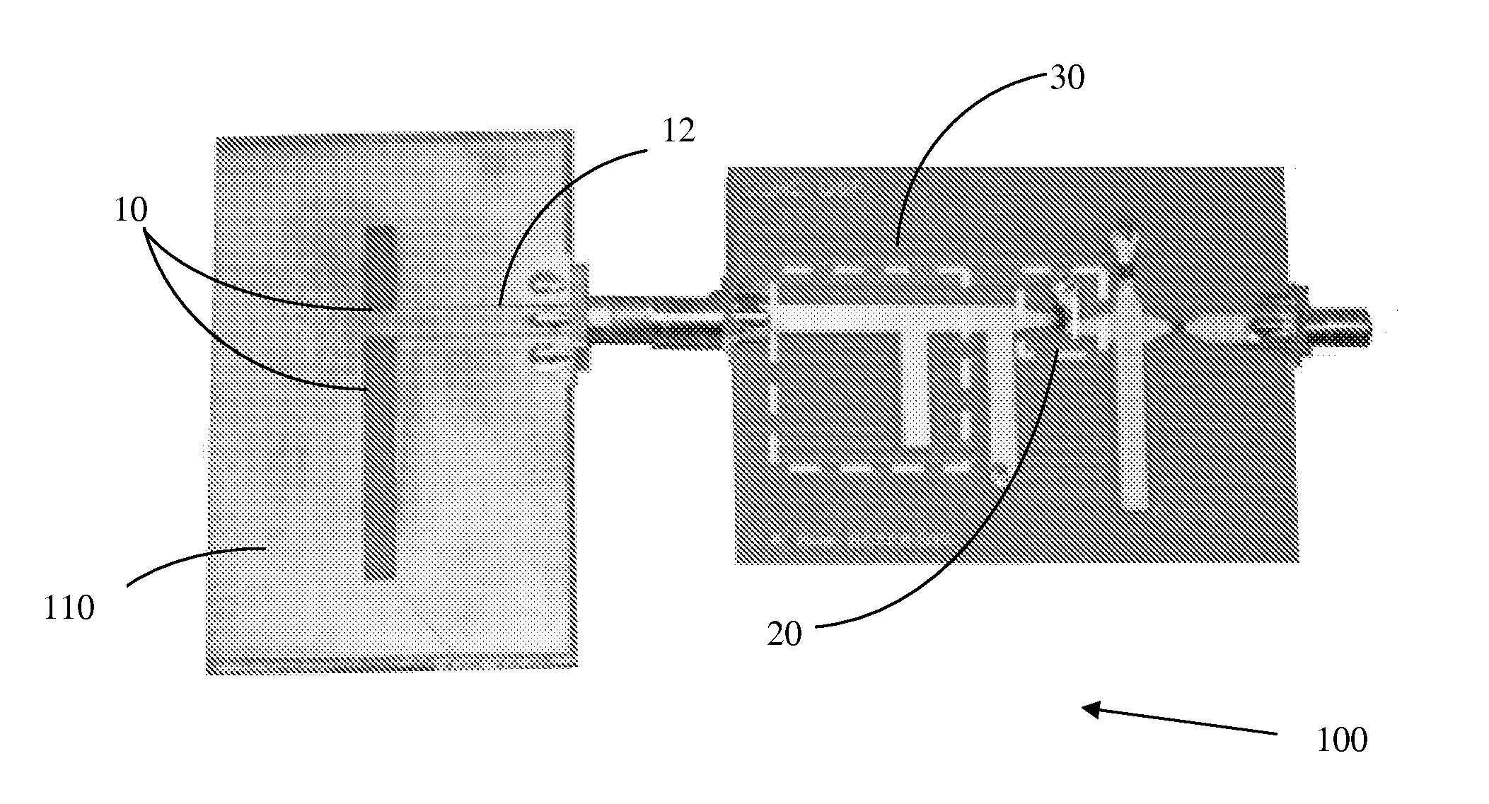
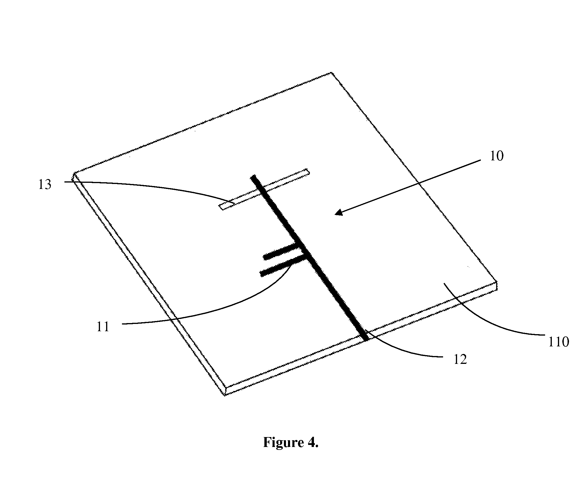
[0060]Energy conversion device 100 comprises antenna 10 or antenna array 10a connected to rectifier 20, forming a rectenna Only a single optical antenna 10 is depicted in FIG. 10, however an array of optical antennas 10a exists. The rectenna comprises an antenna directly engaged to a rectifier 20, or connected to rectifier 20 via transmission lines 30. The rectifier 20 is a metal-insulator-metal diode. Energy conversion device 100 may be connected in parallel, series, or hybrid, such that the currents generated merge, resulting in a useful setup when producing large dimension single energy conversion device 100 is practically prohibitive. The setup allows multiple energy conversion devices to be further integrated into large-scale assemblies where neighbor devices share a common transmission cable 31 to simplify connections. The energy collected by the antennas 10 will be concentrated in the transmission lines 30, whereby the energy is rectified and converted into electricity. The t...

example 2

[0070]A rectenna was placed behind (underneath) a photovoltaic (PV) module. Assuming the conversion efficiency of the PV module is 10-20%, then approximately 80-90% of the solar energy is converted to heat. If a PV panel operates under one sun conditions at 60 degrees centigrade, the panel back surface radiates about 700 W / m2. Assuming the rectenna conversion efficiency is 40%, an additional 280 W / m2 is produced. The combined PV / rectenna output is now about 380 to 480 W / m2 giving a module efficiency of 38-48%.

example 3

[0071]Typical solar hot water heaters operate at 60 to 80 deg. centigrade temperatures. Placement of the rectenna, with an assumed 40% efficiency, underneath the collector produces an electrical output of 280 to 340 W / m2. This also permits use of the device during night or cloudy conditions, as the thermal energy stored, i.e. the hot water, allows more continuous power generation, as seen in Equation (V);

[0072]τ⁡(E)=exp⁡(-2⁢∫x1x2⁢{2⁢m*[qV⁡(x)-E]}1 / 2⁢⁢ⅆx / ℏ),(V)

[0073]In the preceding specification, all documents, acts, or information disclosed does not constitute an admission that the document, act, or information of any combination thereof was publicly available, known to the public, part of the general knowledge in the art, or was known to be relevant to solve any problem at the time of priority.


PUM


Abstract

A rectenna is a combination of an antenna and a rectifier (diode). Because of limitations in nanotechnology fabrication, it has not been possible to develop rectennas that can operate in the visible frequency range. Current work has gone to producing rectennas that operate in the far infrared (thermal emission) frequency range. To harvest solar energy with rectennas to produce electric power and since rectennas cannot operate at such high frequencies, the present invention provides rectenna configurations to overcome this problem.

Description

CROSS REFERENCE TO RELATED APPLICATION[0001]This application claims priority to pending U.S. Provisional Patent Application No. 61 / 050,854, entitled “Rectenna Solar Energy Harvester”, filed on May 6, 2008, the contents of which are herein incorporated by reference.FIELD OF INVENTION[0002]This invention relates to enhancing thermoelectric properties of devices. Specifically, the invention entails using nano-scale fabrication on thermoelectric materials to improve the efficiency of thermoelectric devices.BACKGROUND OF THE INVENTION[0003]Approximately 80% of the world's power is generated by fossil fuel combustion. In the United States, more than 90% of greenhouse gas emissions come from the combustion of fossil fuels. Combustion of fossil fuels also produces other air pollutants, such as nitrogen oxides, sulfur dioxide, volatile organic compounds and heavy metals. Additionally, the cost of producing energy is skyrocketing, due in part to depleting fossil fuel reserves. Clean, renewabl...

Claims


Application Information

Patent Timeline
IPC IPC(8): H01Q1/24
CPCH01Q1/248H01L31/035209H01L31/108
Inventor STEFANAKOS, ELIAS KGOSWAMI, D YOGIBHANSALI, SHEKHAR
Owner UNIV OF SOUTH FLORIDA
Why Eureka
Try Eureka