
Red light fluorescent material and manufacturing method thereof, and white light luminescent device

a technology of red light fluorescent material and manufacturing method, which is applied in the direction of phosphorus oxyacids, energy-saving lighting, sustainable buildings, etc., can solve the problems of increased color temperature, poor color rendering property, and high color temperature of doped cerium, and achieve high color purity and high luminance

Inactive Publication Date: 2012-04-17
CHUNGHWA PICTURE TUBES LTD
View PDF3 Cites 1 Cited by
  • Summary
  • Abstract
  • Description
  • Claims
  • Application Information

AI Technical Summary

Benefits of technology

"The present invention provides a red light fluorescent material with high color purity and high luminance. The material has a unique chemical structure and is excited by a first light to emit a second light. The manufacturing method involves a low sintering temperature, resulting in high chemical stability. The material has a wavelength range of 360 nm to 550 nm, with a relative luminance value of 1.5˜1.9. The material is adapted for a white light emitting diode and can be cooperated with yellow, blue, and green light fluorescent materials. The white light luminescent device has a long lifetime and good color rendering property."

Problems solved by technology

However, the white light generated by the blue light emitting diode and the garnet fluorescent material which is doped with cerium always has the problem of high color temperature.
Especially, when an operating current is elevated, the problem of the increased color temperature is further worsened.
Moreover, as a white light luminescent spectrum does not include a red-colored component, the white light generated by this method has poor color rendering property, and thus has insufficient color rendering property when used as the illuminating light source.
However, the components of the fluorescent powder used herein all contain sulfide, which easily reacts with moisture in the air, so that the dual-fluorescent powder system has poor chemical stability.
In addition, under long term irradiation of the UV light, the dual-fluorescent powder system degrades easily and has the problem of insufficient lifetime.
Besides, as sulfide has poor thermal stability, the fluorescent powder that incorporates sulfide as the main component has limited applications.

Method used


Image

  • Red light fluorescent material and manufacturing method thereof, and white light luminescent device
  • Red light fluorescent material and manufacturing method thereof, and white light luminescent device
  • Red light fluorescent material and manufacturing method thereof, and white light luminescent device

Examples


embodiment 1

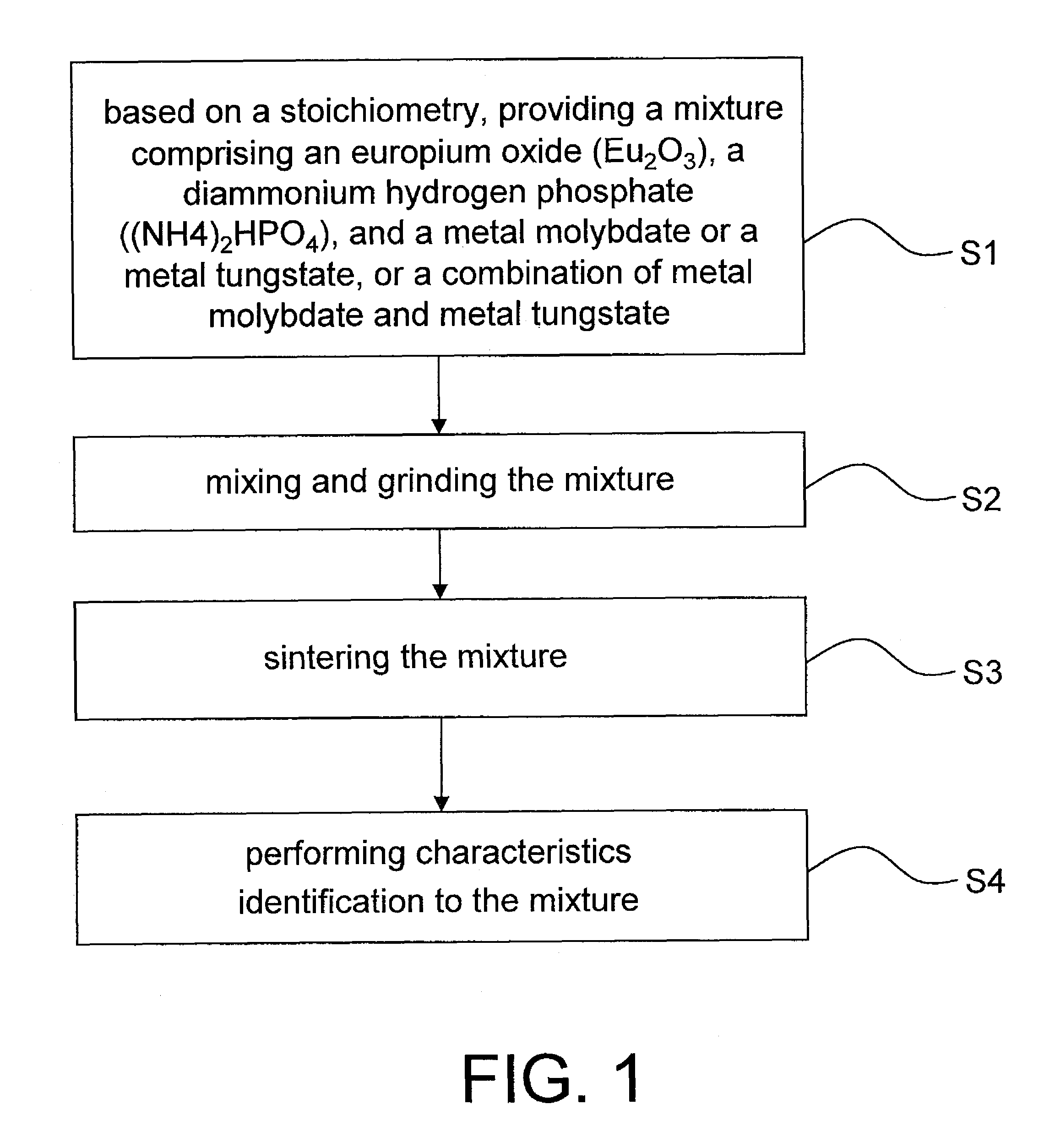
[0056]As illustrated in FIG. 1, a mixture is formed by mixing Na2WO4, Eu2O3, and (NH4)2HPO4 according to stoichiometry. Next, the mixture is disposed on an aluminum oxide crucible after 30 minutes of grinding. Afterwards, the crucible is placed in a high temperature furnace and sintered for 8 hours at 600° C. to obtain a red light fluorescent material Na2Eu(WO4)(PO4).

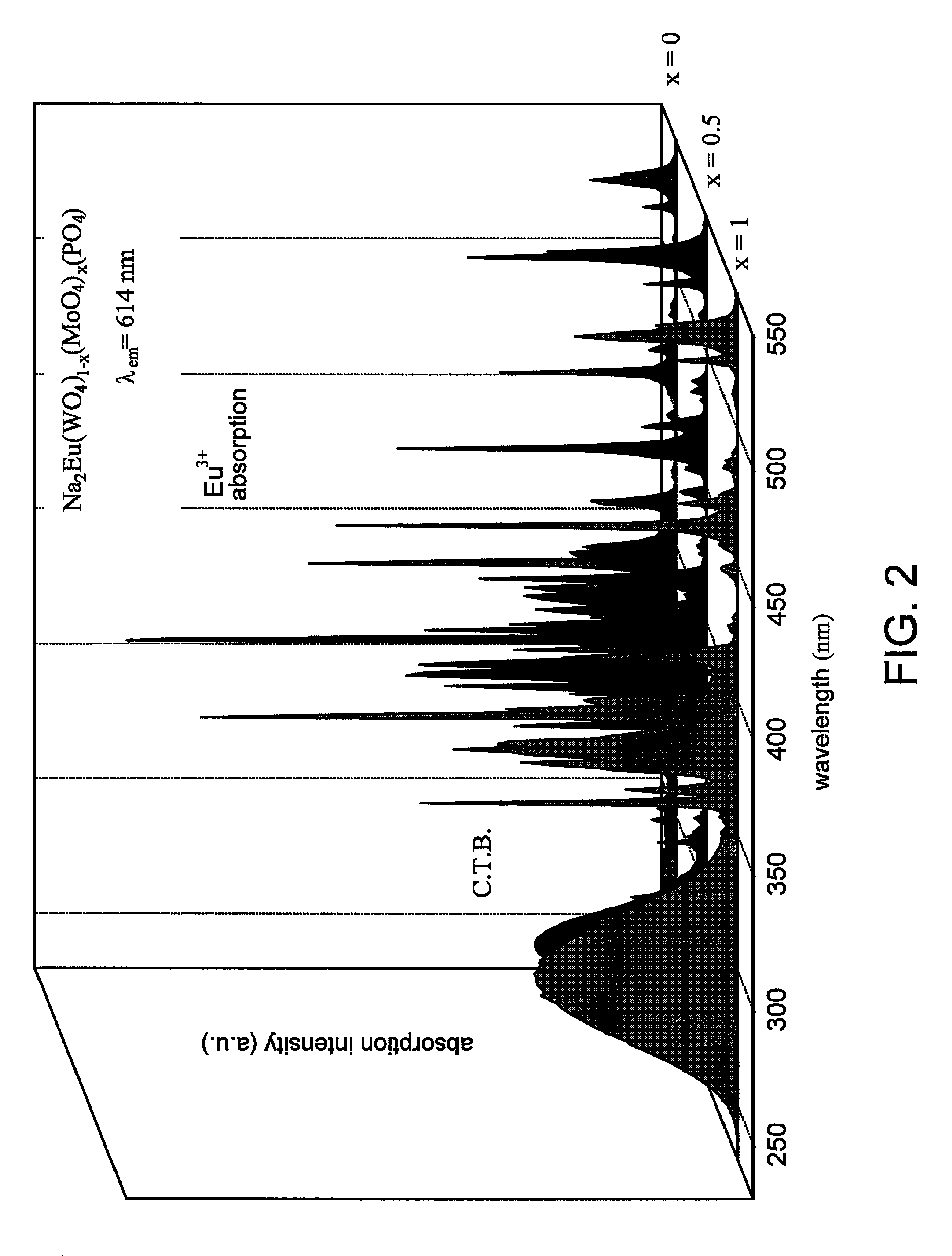
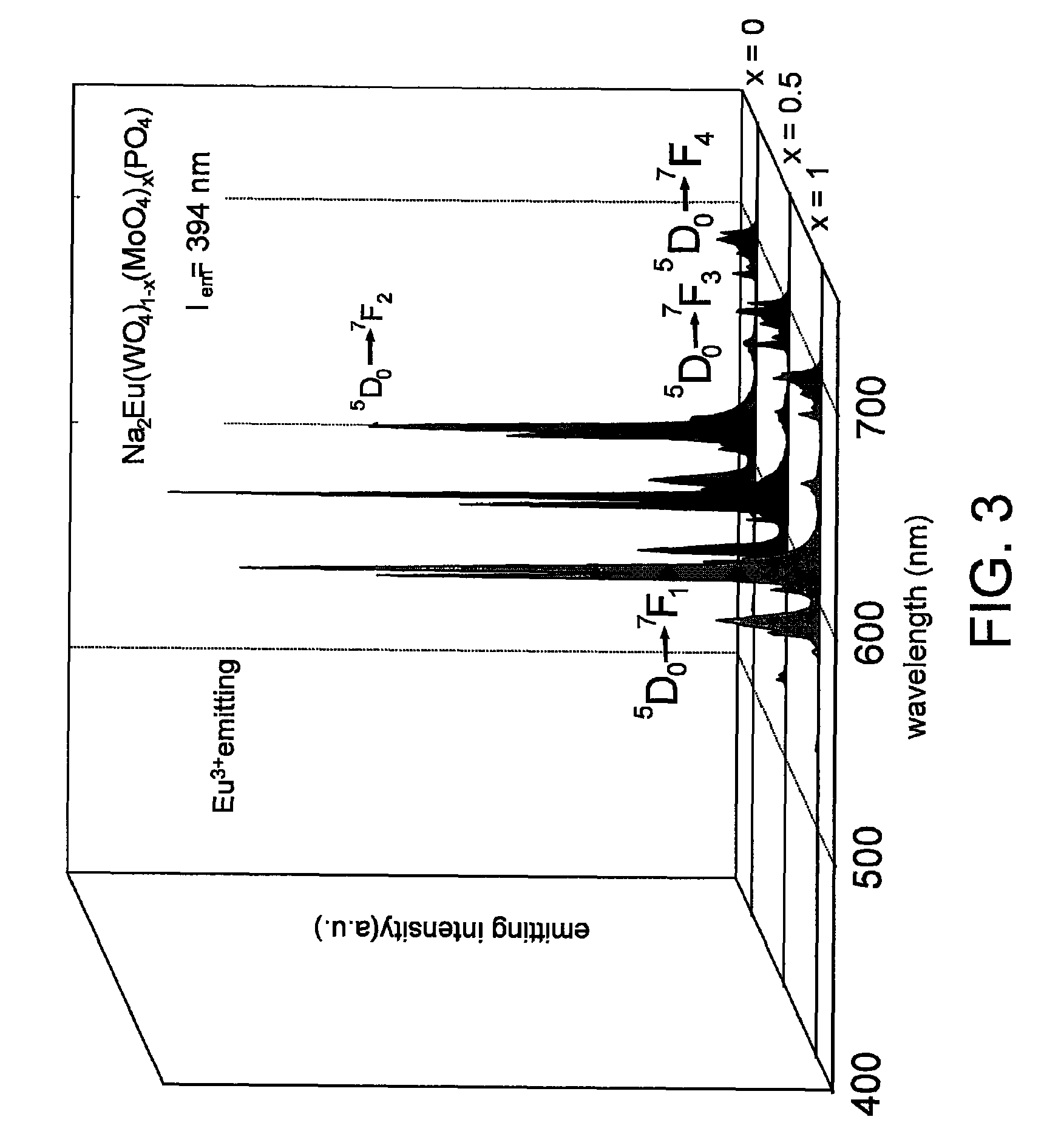
[0057]Thereafter, the UV light-visible light reflection spectroscopy analysis, the fluorescence spectroscopy analysis, the chromaticity coordinate analysis, and the X-ray diffraction analysis are performed on Na2Eu(WO4)(PO4). The result of the fluorescence excited spectroscopy analysis is shown in FIG. 2. The result of the fluorescence emitting spectroscopy analysis is illustrated in FIG. 3. The result of the chromaticity coordinate analysis is illustrated in FIG. 4. The result of the X-ray diffraction analysis is shown in FIG. 5.

[0058]More specifically, according to the fluorescence spectroscopy analysis, a first light...

embodiment 2

[0065]Similar to the embodiment 1, embodiment 2 discloses a manufacturing method as illustrated in FIG. 1. According to the manufacturing method of the present embodiment, a mixture is formed by mixing Na2MoO4, Na2WO4, Eu2O3, and (NH4)2HPO4 according to stoichiometry. After the mixture is ground and sintered, a red light fluorescent material Na2Eu(WO4)0.5(MoO4)0.5(PO4) of the embodiment 2 is obtained.

[0066]Similarly, the characteristics identification is performed on the red light fluorescent material of the embodiment 2, and the results are represented in FIGS. 2˜5. The absorption of the red light fluorescent material Na2Eu(WO4)0.5(MoO4)0.5(PO4) of embodiment 2 is shown at x=0.5.

[0067]It should be noted that the embodiment 2 is characterized in that the mole fraction of metal molybdate to metal tungstate in the composition is 0.5:0.5. The spectrum properties of the red light fluorescent material in the embodiment 2 are similar to those of the red light fluorescent material in the e...

embodiment 3

[0068]Similar to the embodiment 1, embodiment 3 discloses a manufacturing method as illustrated in FIG. 1. According to the manufacturing method of the present embodiment, a mixture is formed by mixing Na2MoO4, Eu2O3, and (NH4)2HPO4 according to stoichiometry. After the mixture is ground and sintered, a red light fluorescent material Na2Eu(MoO4)(PO4) of the embodiment 3 is obtained. Similarly, the characteristics identification is performed on the red light fluorescent material of the embodiment 3, and the results are represented in FIGS. 2˜5. The absorption of the red light fluorescent material Na2Eu(MoO4)(PO4) of the embodiment 3 is shown at x=1.

[0069]The spectrum properties of the red light fluorescent material in the embodiment 3 are similar to those of the red light fluorescent material in the embodiment 1 and thus are not repeated herein. The difference therebetween lies in the different peak intensities. From the results of the foregoing analysis, the red light fluorescent ma...


PUM

PropertyMeasurementUnit
wavelengthaaaaaaaaaa
light wavelengthaaaaaaaaaa

Abstract

A red light fluorescent material adapted for being excited by a first light to emit a red light is provided. The red light fluorescent material has the chemical formula (1) presented below,A2Eu(MO4)(PO4)  (1),in which A represents Li, Na, K, Rb, Cs, or Ag, and M represents Mo, W, or a combination thereof (MoxW(1−x)). The red light fluorescent material can provide a red light with high luminance and good color purity. Moreover, since the composition of the red light fluorescent material includes oxides, the red light fluorescent material has high chemical stability and long lifetime.

Description

CROSS-REFERENCE TO RELATED APPLICATION[0001]This application claims the priority benefit of Taiwan application serial no. 98110900, filed on Apr. 1, 2009. The entirety of the above-mentioned patent application is hereby incorporated by reference herein and made a part of specification.BACKGROUND OF THE INVENTION[0002]1. Field of the Invention[0003]The present invention relates to a red light fluorescent material and a manufacturing method thereof, and a white light luminescent device incorporating the red light fluorescent material. More particularly, the present invention relates to a red light fluorescent material with high color purity, high luminance, and high chemical stability and a manufacturing method thereof, and a white light luminescent device incorporating this red light fluorescent material.[0004]2. Description of Related Art[0005]With recent progress in green technologies, a white light emitting diode now has advantages of low power consumption, compactness, low drivin...

Claims


Application Information

Patent Timeline
Patent Type & Authority Patents(United States)
IPC IPC(8): C09K11/08C09K11/70C09K11/54
CPCC01B25/26C09K11/7736Y02B20/181H01L33/502Y02B20/00
Inventor CHIU, CHUANG-HUNGCHEN, TENG-MINGMO, CHI-NENG
Owner CHUNGHWA PICTURE TUBES LTD
Learn More