Magnetic element with thermally assisted writing

a technology of magnetic tunnel junction and magnetic valve, which is applied in the direction of magnetic recording, static storage, instruments, etc., can solve the problems of limited capacity, limited integration possibility, and inability to guarantee the stability of the free layer's magnetization with respect to heat fluctuations, so as to minimize the risks of breakdown and ageing, the effect of reducing the risk of aging

Active Publication Date: 2012-07-24
CROCUS TECHNOLOGY
View PDF15 Cites 9 Cited by
  • Summary
  • Abstract
  • Description
  • Claims
  • Application Information

AI Technical Summary

Benefits of technology

[0045]The aim of the present invention is to propose an innovative system making it possible to maintain a sufficient considerable current injected through the memory point whilst minimizing as much as possible the voltage at the terminals of the ultra-thin oxide layer constituting the ultra-thin tunnel barrier. This will allow to achieve both a spin torque and / or temperature rise sufficiently efficient for writing the memory point and to minimize the risks of breakdown and ageing of the tunnel barrier.
[0053]Using such layers with a high electric resistivity and highly reduced thickness, notably on the order of or less than one nanometer, enables the resistance of the staking of the magnetic tunnel junction to be optimized without at the same time affecting the characteristic resistance of the layer constituting the tunnel barrier and provided between the storage layer and the reference layer.
[0057]The thickness of these oxide or nitride layers is preferably less than one nanometer in order to obtain layers that are preferably discontinuous, allowing the continuity of the magnetic properties of the ferromagnetic or antiferromagnetic layers to which they are introduced to be maintained.
[0059]This solution notably has the advantage over the prior art of a voltage gain of typically 10 to 50% when one or several highly resistive thin layers are introduced in the magnetic junction. This results in a reduction of the stress induced during the writing operation as well as a reduction of the aging effects of the junction. The presence of one or several thin layers in the magnetic element of the invention also allows the magnetic junction to be heated more efficiently.

Problems solved by technology

This technology, thanks to its architecture, enables non-volatile memories to be made with a simple technology, albeit of limited capacity.
The fact that the memory elements or points are connected serially along each line limits the possibility of integration, since the signal gets weaker and weaker as the number of memory elements or points increases.
As the distribution function of the switching fields for all of the memory points is wide (it is indeed not uniform because of manufacturing constraints and intrinsic statistical fluctuations), it is necessary that the magnetic field on the selected memory point be greater than the highest distribution switching field, with the risk of accidentally reversing certain memory points located on the corresponding line or column, where the switching field located in the lower part of the distribution is weaker than the magnetic field generated by the line or column alone.Furthermore, considering that in general, the average value of the switching field increases when the size of the memory points diminishes, which one strives to achieve for reasons of space and cost, an ever higher current is expected in future product generations.
Therefore, the electric power required for operating these memories will be all the greater as integration becomes more and more advanced.Finally, the stability of the magnetization of the free layer with respect to heat fluctuations is no longer guaranteed when the size of the memory point diminishes.
By doing this, however, the magnetic field necessary for the magnetic switching increases, which results in an increased electric consumption for generating the field necessary to the magnetic switching.
Despite these advantages, there are however some difficulties in terms of manufacturing technology.
The main difficulty is linked to the need to apply a current pulse through the magnetic tunnel junction in order to heat the memory point to a temperature greater than the critical temperature of the antiferromagnetic layer pinning the storage layer.
This current pulse is liable to subject the ultra-thin oxide layer constituting the tunnel barrier to a considerable electric stress.
Furthermore, even if the voltage applied onto the tunnel barrier is lower than its breakdown voltage, the stress linked to the electric current pulse can result in considerable aging effects in the long term, notably after a great number of writing cycles.
However, this double magnetic tunnel junction has an increased complexity as regards the making of the stack and of the memory cells, notably during the burning phase of the memory point.
Furthermore, using a double magnetic tunnel junction has disadvantages for an architecture of writing based on spin transfer.
Indeed, if the magnetizations of the two magnetic reference layers are blocked in anti-parallel fashion, the efficiency of the spin torque is considerable but the value of the resistances of the two memory states becomes comparable and, subsequently, the reading margin finds itself drastically reduced.

Method used


Image

  • Magnetic element with thermally assisted writing
  • Magnetic element with thermally assisted writing
  • Magnetic element with thermally assisted writing

Examples


Embodiment Construction

[0065]The prior state of the art relative to random access magnetic memories has been abundantly described in the preamble of the present invention.

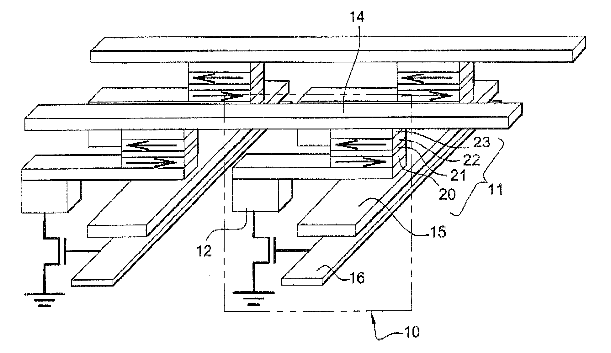
[0066]In doing so, and with the aim of simplifying the present description, a single memory point constituting such magnetic memories will be descried hereinafter in more detail.

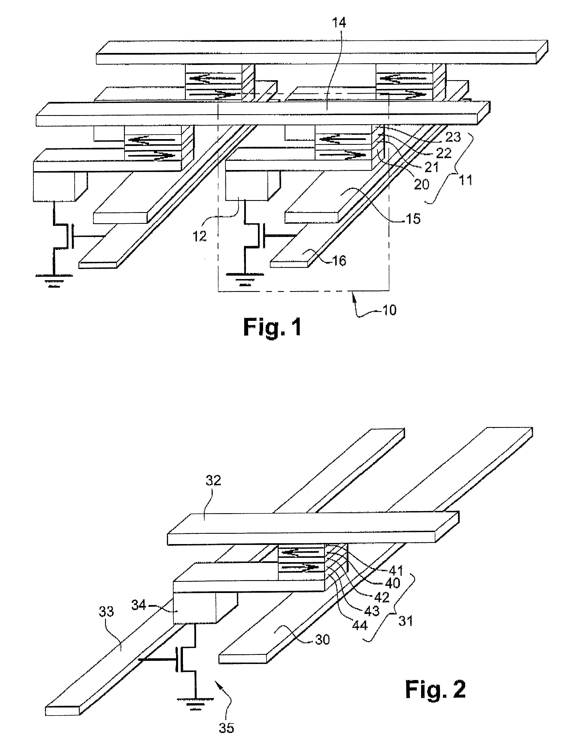
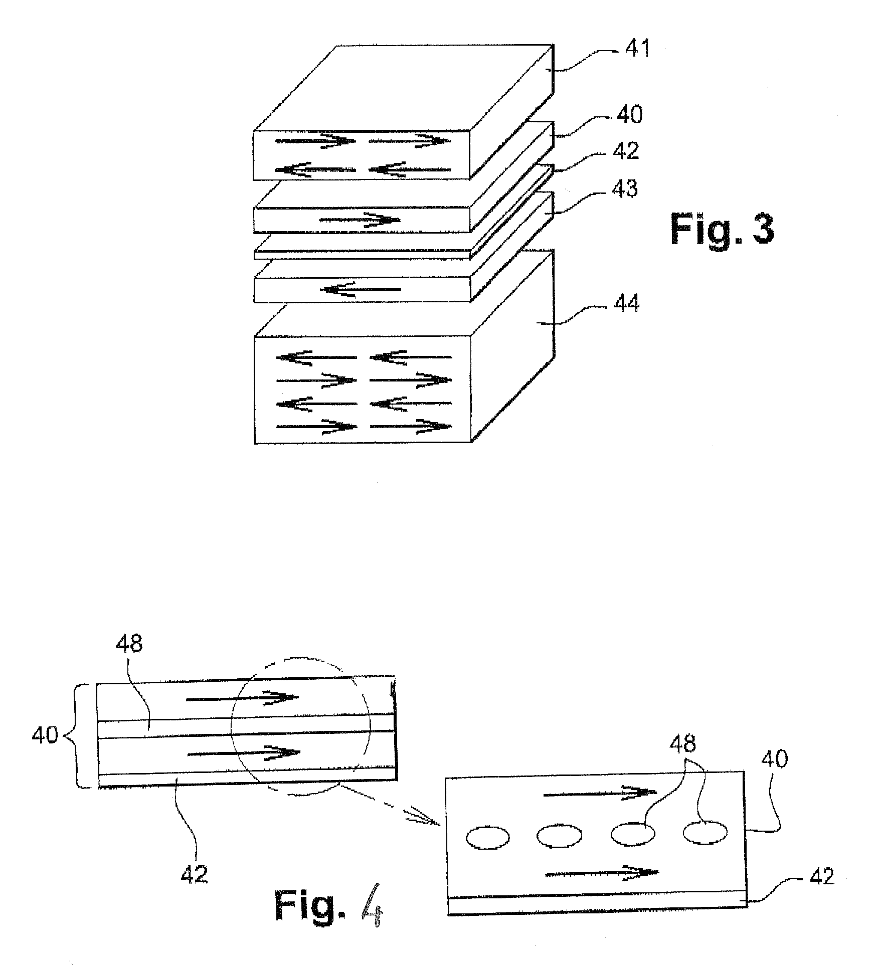
[0067]As has already been said, the latter is fundamentally constituted of a magnetoresistive magnetic element, preferably a magnetic tunnel junction 31. The later comprises a tunnel barrier 42, selected in the group including among others aluminum oxides Al2O3 and magnesium oxides MgO.

[0068]Alternatively, the layer 42 separating the reference layer 43 from the storing layer 40 can be of semi-conducting nature (for example on the basis of silicon or germanium or of GaAs) or a heterogeneous metal / oxide layer, such as layers having a confined current path developed in the context of magnetoresistive reader heads for hard drives. These are for example constituted of...


PUM


Abstract

Magnetic element with thermally-assisted magnetic-field writing or thermally-assisted spin-transfer writing, comprising: a reference magnetic layer having a fixed direction magnetization; a storage magnetic layer exchange-pinned with an antiferromagnetic layer, wherein the magnetization direction of the storage layer can vary when said element can be heated to a temperature at least higher than a critical temperature of the antiferromagnetic layer; a tunnel barrier, provided between the reference layer and the storage layer; wherein the magnetic reference layer, and / or the magnetic storage layer includes at least one electrically-resistive thin layer for heating the magnetic element. The magnetic element disclosed herein has a voltage gain of typically 10 to 50% compared to conventional magnetic elements and shows a reduction of the stress induced during a writing operation as well as a reduction of the aging.

Description

TECHNICAL FIELD[0001]The present invention relates to the field of magnetic elements with magnetic tunnel junction or spin valve, such as those used in magnetic non-volatile random access memories (NVRAM), for storing, reading and writing data in electronic systems in known ways. More specifically, it applies to magnetic random access memories, traditionally designated by the acronym MRAM, constituted of a set of memory points each formed by a magnetic tunnel junction, also designated by the acronym MTJ.[0002]Hereinafter, a “magnetic element” is understood to be a stacking of magnetic layers having at least one so-called “reference” layer, one so-called “storage” layer and between them an insulation or semiconducting layer or a layer having a confined current path. The definition of the notion of reference layer and of storage layer will appear more precisely in the present description that follows.BACKGROUND[0003]Magnetic MRAM memories have met with renewed interest following the d...

Claims


Application Information

Patent Timeline
Patent Type & Authority Patents(United States)
IPC IPC(8): G11C11/00
CPCG11C11/16G11C11/1675
Inventor NOZIERES, JEAN-PIERREPREJBEANU, IOAN LUCIAN
Owner CROCUS TECHNOLOGY
Why Eureka
Try Eureka