Detecting a disturbance in the phase of light propagating in an optical waveguide

a technology of optical waveguide and phase, applied in the field of apparatus and method for detecting a disturbance in the phase of light propagating in an optical waveguide, can solve the problems of inability to readily obtain cheap sources of very coherent light, undesirable differences due to changes in backscattering of incoherent light, and the level of wanted signal in the desired comparison between photodetector signals for successive light pulses, etc., to achieve better spatial resolution, faster response, and better signal-to-noi ratio ratio ratio

Active Publication Date: 2012-09-11
VIAVI SOLUTIONS INC
View PDF15 Cites 25 Cited by
  • Summary
  • Abstract
  • Description
  • Claims
  • Application Information

AI Technical Summary

Benefits of technology

[0023]So, the invention recognises that it can be more effective to carry out phase sensitive OTDR using partially coherent light pulses rather than very coherent light pulses. Comparison of signals representing the intensity of light backscattered from partially coherent light pulses allows good visibility of changes in the rate of change of phase of light propagating along the waveguide between successive light pulses but, crucially, allows better signal-to-noise ratio (SNR) to be achieved for the detected signal and thus allows better spatial resolution and a faster response than obtainable from very coherent light pulses.
[0024]Importantly, the spectral width of the light pulses defined by the invention means that the potential effects of Brillouin scattering are significantly reduced in comparison to the spectrally narrower optical pulses used in the prior art. Ideally, the spectral width of the light pulses should be greater than the Brillouin Gain bandwidth for the optical waveguide, which is around 17 MHz for a silica optical fibre. Indeed, light pulses sent along the waveguide preferably have a spectral width of the order of around 1 GHz to 10 GHz or more ideally the light pulses sent along the waveguide have a spectral width of around 7.5 GHz. This allows the light pulses to have greater power than those used in the prior art. Typically, the power of the light pulses is of the order of around 0.1 W and 10 W or more ideally around 2 W. It also allows the light pulses to be shorter, e.g. to have spatial length of the order of around 1 m and 100 m, preferably of the order of around 1 m and 10 m or ideally around 1 m.
[0025]Usefully, the spectral width of the light pulses is defined by filtering the light output by the light source. More specifically, the apparatus may further comprise an optical filter for filtering the light before it reaches the photodetector, wherein the optical bandwidth of the optical filter is less than the spectral width of the light source. Likewise, the method may further comprise filtering the light before it reaches the photodetector using a filter having an optical bandwidth less than the spectral width of the light source. This filtering should be distinguished from conventional filtering to eliminate spontaneous emission or such like, which are outside of the main spectrum of light emitted by a light source. Here, importantly, the main spectrum of light emitted by the light source is narrowed. In other words, the linewidth of the light is reduced.
[0038]Preferably, the optical filter is positioned to filter the backscattered light. This is advantageous as it allows the spectral width of light traveling in the optical waveguide to be greater than that of the detected backscattered light. As spectral width is related to coherence, the filtering can ensure that the detected light is sufficiently coherent to that the temporal speckle pattern can be detected. At the same time, the light traveling in the waveguide can be relatively spectrally broad so that non-linear effects in the optical waveguide, such as Brillouin scattering, can be reduced.

Problems solved by technology

On the other hand, for phase sensitive OTDR, backscattered light from any incoherent component of the coherent light pulses does not contribute to the temporal speckle pattern and therefore reduces the level of the wanted signal in the desired comparison between photodetector signals for successive light pulses.
The presence of differences due to changes in backscattering of incoherent light is undesirable.
One problem with this implementation is that cheap sources of very coherent light are not readily available.
Bespoke light sources have been designed to try to meet the coherence requirements of U.S. Pat. No. 5,194,847 and the above paper, e.g. as described in the paper “Spectrally Stable Er-Fibre Laser for Application in Phase Sensitive Optical Time-Domain Reflectometry”, Kyoo Nam Choi et al, IEEE Photonics Technology Letters, Vol. 15, No. 3, Mar. 2003, but these tend to be expensive.
They are also prone to frequency drift.
If frequency drift causes the frequency of the light source to change too much between successive light pulses, false differences between successive photodetector signals can be generated.
Naturally, this limits the effectiveness of the technique.
Another problem is that the power of light pulses that can be launched into the optical fibre from coherent light sources is limited by various phenomena, particularly so-called “non-linear effects”.
Notably, Brillouin scattering causes light to be inelastically backscattered (e.g. converted to backwardly propagating light of a different wavelength to that of the light pulse), resulting in attenuation of the light pulse as it travels along the optical fibre.
This therefore limits the power of the light pulses used in the implementation described in U.S. Pat. No. 5,194,847 and the above paper.
However, this reduces temporal resolution.
Furthermore, it becomes impossible to resolve changes that are faster than the duration of the averaging time.
Applications such as detection of acoustic waves and so on cannot therefore be realised.

Method used


Image

  • Detecting a disturbance in the phase of light propagating in an optical waveguide
  • Detecting a disturbance in the phase of light propagating in an optical waveguide
  • Detecting a disturbance in the phase of light propagating in an optical waveguide

Examples


first embodiment

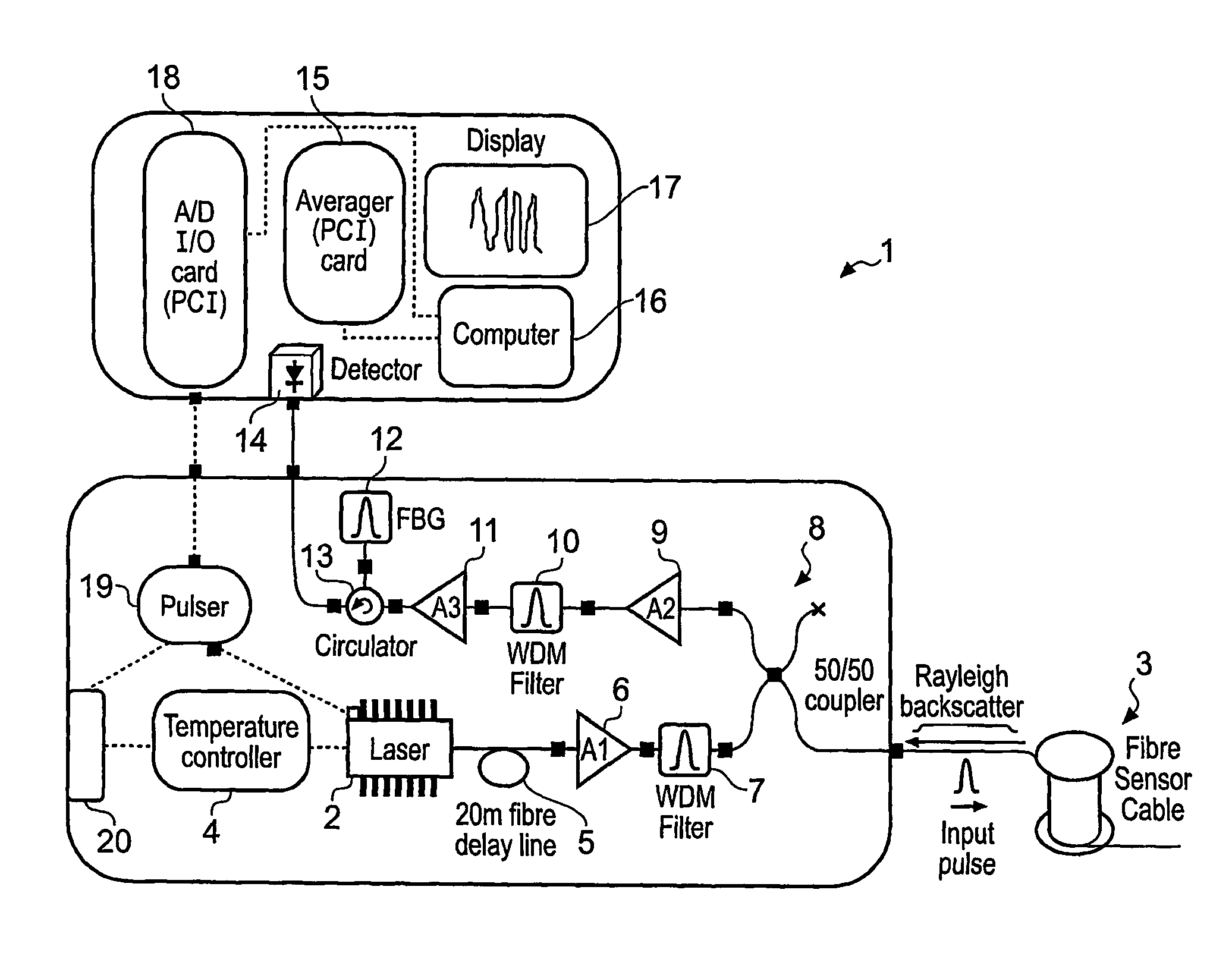
[0048]Referring to FIG. 1, a partially coherent Optical Time Domain Reflectometry (OTDR) apparatus 1 according to the present invention has a light source comprising a directly modulated semiconductor Distributed FeedBack (DFB) laser diode 2 for transmitting light pulses along a monomode optical fibre 3. DFB laser diodes are common in optical wavelength division multiplexed (WDM) telecommunication networks and, in this embodiment, the DFB laser diode 2 is of the type typically used in 2.5 Gbps WDM telecommunications. A temperature stabilising unit comprising a Peltier element 4 is provided to control the temperature of the DFB laser diode 2. As the temperature of the DFB laser diode 2 changes, so does the wavelength of the light pulses it transmits. The Peltier element 4 enables precise wavelength control over around a 1 to 2 nm range, so that the wavelength of the light pulses can be adjusted. Typically, the wavelength of the light pulses is around that for which the monomode optic...

second embodiment

[0071]In one version of the second embodiment, the photodetector 14 is an InGaAs p-i-n photodetector with a three stage transimpedance amplifier, such as model 2053 from New Focus, having an electronic bandwidth of 700 kHz, a voltage responsivity 1.89×10⁶ V / W and an NEP of 0.34 pW / rtHz. For light pulses of duration 500 ns (50 m) launched into the optical fibre 3 with power 500 mW, the predicted SNR is about 35 dB. The logarithm of the reciprocal of visibility parameter VI is equivalent to a signal level around 18 dB, which means that the SNR is around 17 dB higher and the temporal speckle pattern should be easily distinguishable from the predicted noise.

[0072]In another version of the second embodiment, the photodetector 14 is an InGaAs avalanche photodiode with an integrated hybrid preamplifier, such as model C30662E from Perkin Elmer, having an electronic bandwidth of 50 MHz, a voltage responsivity 3.4×10⁵ V / W and an NEP of 0.13 pW / rtHz. IF the electronic bandwidth is limited to 7...


PUM

PropertyMeasurementUnit
spatial lengthaaaaaaaaaa

Abstract

A partially coherent Optical Time Domain Reflectometry (OTDR) apparatus has a light source comprising a directly modulated semiconductor Distributed FeedBack (DFB) laser diode for transmitting partially coherent light pulses along a monomode optical fibre. Light Rayleigh backscattered from the light pulses as they travel along the optical fibre is output from the end of the fibre into which the light pulses are transmitted to a Fibre Bragg Grating (FBG) filter. The FBG filter reduces the supectral width of light received at a photodetector. In one embodiment, the supectral width of the FBG filter is around one fifth of the supectral width of the light pulse after it has travelled around 1 km along the optical fibre. As a consequence of reducing the supectral width of the light received at the photodetector, the FBG filter increases the temporal coherence of the light. So, the FBG filter can ensure that the detected light is sufficiently coherent that a temporal supeckle pattern can be detected at the photodetector. At the same time, the light traveling in the optical fibre can be relatively supectrally broad so that non-linear effects in the optical fibre, such as Brillouin scattering, can be reduced.

Description

CROSS REFERENCE TO RELATED APPLICATIONS[0001]The present application is a National Phase Application of International Application No. PCT / GB2007 / 004253 filed Nov. 8, 2007, which claims priority to Great Britain Patent Application No. 0622207.9 filed Nov. 8, 2006, which applications are incorporated herein fully by this reference.FIELD OF THE INVENTION[0002]This invention relates to an apparatus and method for detecting a disturbance in the phase of light propagating in an optical waveguide. More particularly, but not exclusively, the invention relates to improvements to phase sensitive Optical Time-Domain Reflectometry (OTDR) for detecting an externally induced, time-varying disturbance in the phase of light propagating in a monomode optical fibre.BACKGROUND TO THE INVENTION[0003]OTDR is an established technique for analysing the propagation of light in an optical fibre. In the telecommunications industry, the technique is widely used to detect and locate damage to optical fibres. T...

Claims


Application Information

Patent Timeline
Patent Type & Authority Patents(United States)
IPC IPC(8): G01N21/00
CPCG01M11/3118
Inventor KANELLOPOULOS, SOTIRIS EMILSHATALIN, SERGEY VLADIMIR
Owner VIAVI SOLUTIONS INC
Why Eureka
Try Eureka