Organic electroluminescent device, liquid crystal display and illuminating device

a liquid crystal display and electroluminescent element technology, applied in the direction of discharge tube luminescnet screen, discharge tube/lamp details, instruments, etc., can solve the problems of organic el element employing phosphorescence light mission material, organic el element markedly deteriorated in light emission property, element deterioration, etc., to achieve excellent heat resistance during sealing process, less non-uniform color, and thin and compact sealing structure

Active Publication Date: 2012-11-13
MERCK PATENT GMBH
View PDF8 Cites 0 Cited by
  • Summary
  • Abstract
  • Description
  • Claims
  • Application Information

AI Technical Summary

Benefits of technology

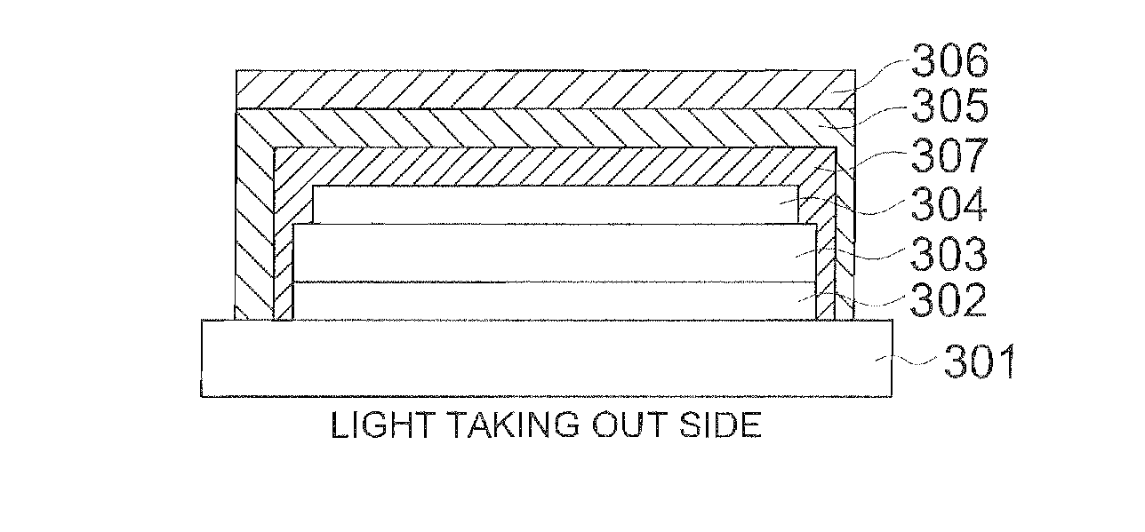
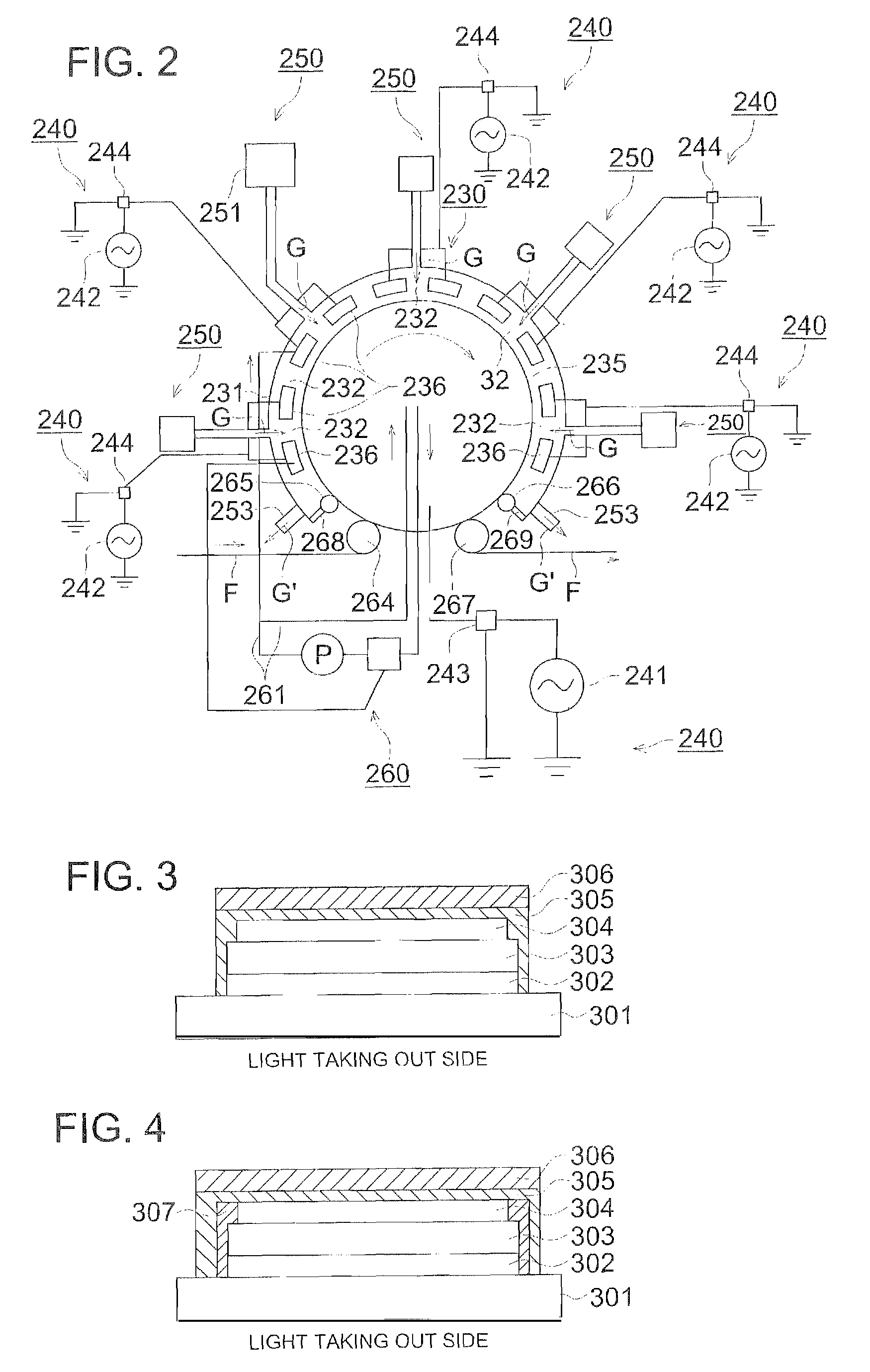
[0032]An organic electroluminescent device can be provided which has thin and compact sealing structure, excellent in heat resistance during sealing process and less non-uniform color, particularly an organic electroluminescent device having high luminescent phosphorescent material, a liquid crystal display and an illuminating element using the organic electroluminescent device, by this invention.

Problems solved by technology

The organic EL element is markedly deteriorated in its light emission property by exposure to air or moisture.
The organic EL element employing phosphorescence light mission material is also deteriorated markedly by exposure to air or moisture.
Volume within sealed space changes by expansion and shrink due to temperature or atmospheric pressure since the sealed space is atmosphere pressure, and, adhesion part is suffered from stress which causes cracks or peeling at adhesion part by repeating the expansion and shrink, and therefore, oxygen or moisture penetrated from the outside, consequently the element is deteriorated.
Further, pressure change by expansion and shrink influences to a barrier film to induce generation of cracks of the barrier layer.

Method used


Image

  • Organic electroluminescent device, liquid crystal display and illuminating device
  • Organic electroluminescent device, liquid crystal display and illuminating device
  • Organic electroluminescent device, liquid crystal display and illuminating device

Examples


example 1

Preparation of Organic EL Device 1

[0223]For preparing an anode, an electrode was patterned on a glass substrate having a size of 30 mm×30 mm and a thickness of 0.7 mm and an ITO (indium tin oxide) layer of 120 nm formed thereon and the transparent substrate having the ITO transparent electrode was washed by isopropyl alcohol while applying ultrasonic wave, dried by desiccated nitrogen gas and subjected to UV-ozone washing. Then the transparent substrate was fixed on the substrate holder of a vacuum deposition apparatus available on the market.

[0224]Suitable amount of constitution materials of each of the layers were separately charged in each of crucibles, respectively. The crucibles made from a heat resistive material prepared by molybdenum or tungsten was used.

[0225]Then the pressure in the vacuum deposition apparatus was reduced by a vacuum degree of 4×10⁻⁴ Pa and the crucible containing m-MTDATA (Tg: 75° C.) was heated by applying electric current for depositing m-MTDATA onto th...

example 2

[0250]The organic EL devices prepared in Example 1 were the devices each containing three kinds of light emission substances each different in the wavelength of the emitting light and emitting white light. Situation of the light emission of Organic EL Devices 1 and 2 at the time of 30 minutes after beginning of thermal curing was observed by the microscope. As a result of that, it was observed that Organic EL Device 1 was larger in the ununiformity of color in the light than that in Organic EL Device 2. Namely, it is understood that the Organic EL Device 2 of the invention is a device superior in the chromaticity stability in the light emitting surface.

[0251]The organic EL device of the invention gives suitable properties when the device is used as the backlight of a liquid crystal display.


PUM


Abstract

This invention provides an organic electroluminescent element that has a thin and compact sealing structure and is excellent in heat resistance in sealing, particularly a high-brightness organic electroluminescent element comprising a phosphorescence emitting substance, and a liquid crystal display device and lighting equipment using the same. The organic electroluminescent element comprises a substrate and a first electrode, one or more organic layers including a luminescent layer, and a second electrode provided on the substrate. An adhesive layer is disposed on the whole area of a light emitting surface and remote from the light takeout side in the organic electroluminescent element, and a flexible film having a barrier film is applied thereto to form the light emitting surface. The organic electroluminescent element is characterized in that at least one of the luminescent material contained in the luminescent layer is phosphorescence emitting substance, and not less than 80% by mass of the organic material constituting the organic layer has a glass transition temperature of 100° C. or above.

Description

[0001]This is a U.S. National Phase Application under 35 U.S.C. 371 of International Application PCT / JP2006 / 320472 filed on Oct. 13, 2006.[0002]This Application claims the priority of Japanese Application No. 2005-312467, filed Oct. 27, 2005, the entire content of which is hereby incorporated by reference.TECHNICAL FIELD[0003]The present invention relates to an organic electroluminescent element, a liquid crystal display and an illuminating device.TECHNICAL BACKGROUND[0004]Electroluminescent displays are used as light emitting type electronic display device (ELD). As the constituting element of the ELD, an inorganic electroluminescent element (inorganic EL element) and an organic electroluminescent device (organic EL device) are cited. The inorganic EL device has been used as a planar light source though high alternative voltage is required for driving such the light emitting device.[0005]The organic EL device is an element having a light emission layer placed between a cathode and ...

Claims


Application Information

Patent Timeline
Patent Type & Authority Patents(United States)
IPC IPC(8): H01J1/62
CPCC09K11/06H01L51/5246H01L51/5256H05B33/14C09K2211/1007C09K2211/1011C09K2211/1014C09K2211/1029C09K2211/1044C09K2211/1092C09K2211/185C09K2211/186G02F1/133602H01L51/5016H01L51/5036H10K50/125H10K50/11H10K2101/10H10K50/8445H10K50/8426
Inventor NAKAYAMA, TOMOYUKITAKASHIMA, NOBUHIKOMURAYAMA, MASAAKI
Owner MERCK PATENT GMBH
Why Eureka
Try Eureka