Fibrous non-woven polymeric material

a non-woven polymer and fibrous technology, applied in the direction of powder delivery, packaging goods, immobilised enzymes, etc., can solve the problems of insufficient control of material homogeneity and reproducibility, low total yield of the electrospinning process, and complex manufacturing process

Active Publication Date: 2013-03-05
SCHEER INGO +1
View PDF4 Cites 18 Cited by
  • Summary
  • Abstract
  • Description
  • Claims
  • Application Information

AI Technical Summary

Benefits of technology

[0008]To overcome the limitations of the prior art a new process is provided to produce non-woven biocompatible fibrous materials (structures or memb

Problems solved by technology

Electrospinning is however a rather complex and time-consuming manufacturing process, which requires applying a high voltage and provides insufficient control of material homogeneity and reproducibility.
In particular when small fibers, such as nanosize fibers, are produced the total yield of the electrospinning process is very low and process scale-up cannot be easily achieved. FIG. 1A represents a scanning electron microscopy (SEM) image of a portion o

Method used


Image

  • Fibrous non-woven polymeric material
  • Fibrous non-woven polymeric material
  • Fibrous non-woven polymeric material

Examples


example 1

[0074]A polymer composition (composition A) was prepared from two biodegradable polymeric components. 5% by weight of a poly(lactide co glucolide) 50 / 50 copolymer and poly(ethylene glycol) was dissolved in acetone. A fibrous membrane was formed on several stents according to the method of the present invention. The membrane was applied in five passes. It could be seen that a layer with more homogeneous surface features was produced.

[0075]The stents were weighted before and after formation of the membrane and the measurement data were analyzed. As shown in Table 2 the average weight of the produced fibrous membranes was 233 μg and the coefficient of variation 11.8%.

[0076]

TABLE 1Stent #Membrane Weight [μg]12652217325942285200

[0077]

TABLE 2ResultsAverage233.8COV [%]11.8

[0078]The outer surface of the covered stents was inspected under a digital microscope and pictures were taken from a portion of the covered stent at different magnifications as shown in FIGS. 10A-10D. It can be seen that...

example 2

[0079]A fibrous membrane composed of a biostable polymer composition was formed on cardiac stents. The polymer composition (composition B) was comprised of 2.5% by weight of poly(ethylene co vinyl acetate) with 40% Vinyl acetate dissolved in tetrahydrofuran.

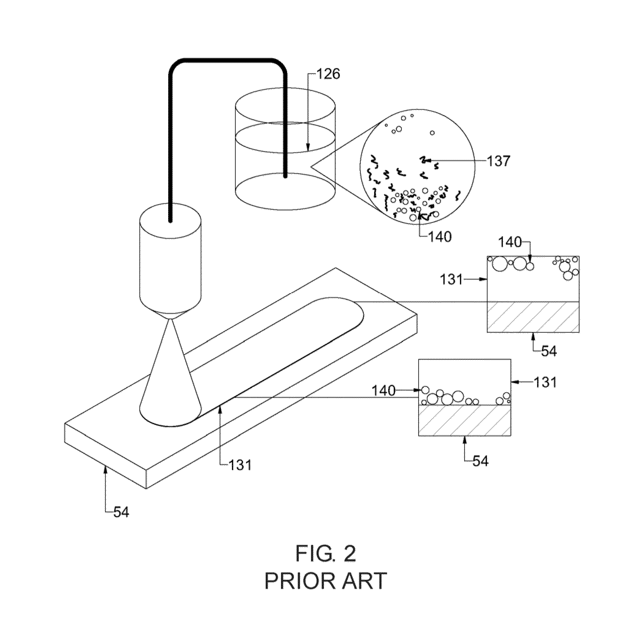
[0080]The formation of the fibrous membrane was monitored and controlled using a spray diagnostic apparatus as described in US. Pat. App. No. 60 / 674,005. It was observed that the majority of the generated particles have a string or strand like shape, which were transported to the wire mesh (stent) so that a fibrous membrane was formed covering the openings of the wire mesh. FIG. 8 is a screenshot taken during the fiber deposition step on the stent. The size distribution of the fibers, which was measured prior to deposition, is displayed in FIG. 9. The outer surface of the covered stent was inspected under a digital microscope and pictures were taken from a portion of the stent at different magnifications as show in FIGS. 11A-11B....

example 3

[0081]A fibrous membrane composed of a biostable polymer composition was formed on cardiac stents. The composition (composition C) was composed of 2.5% by weight of poly(urethane) dissolved in tetrahydrofuran.

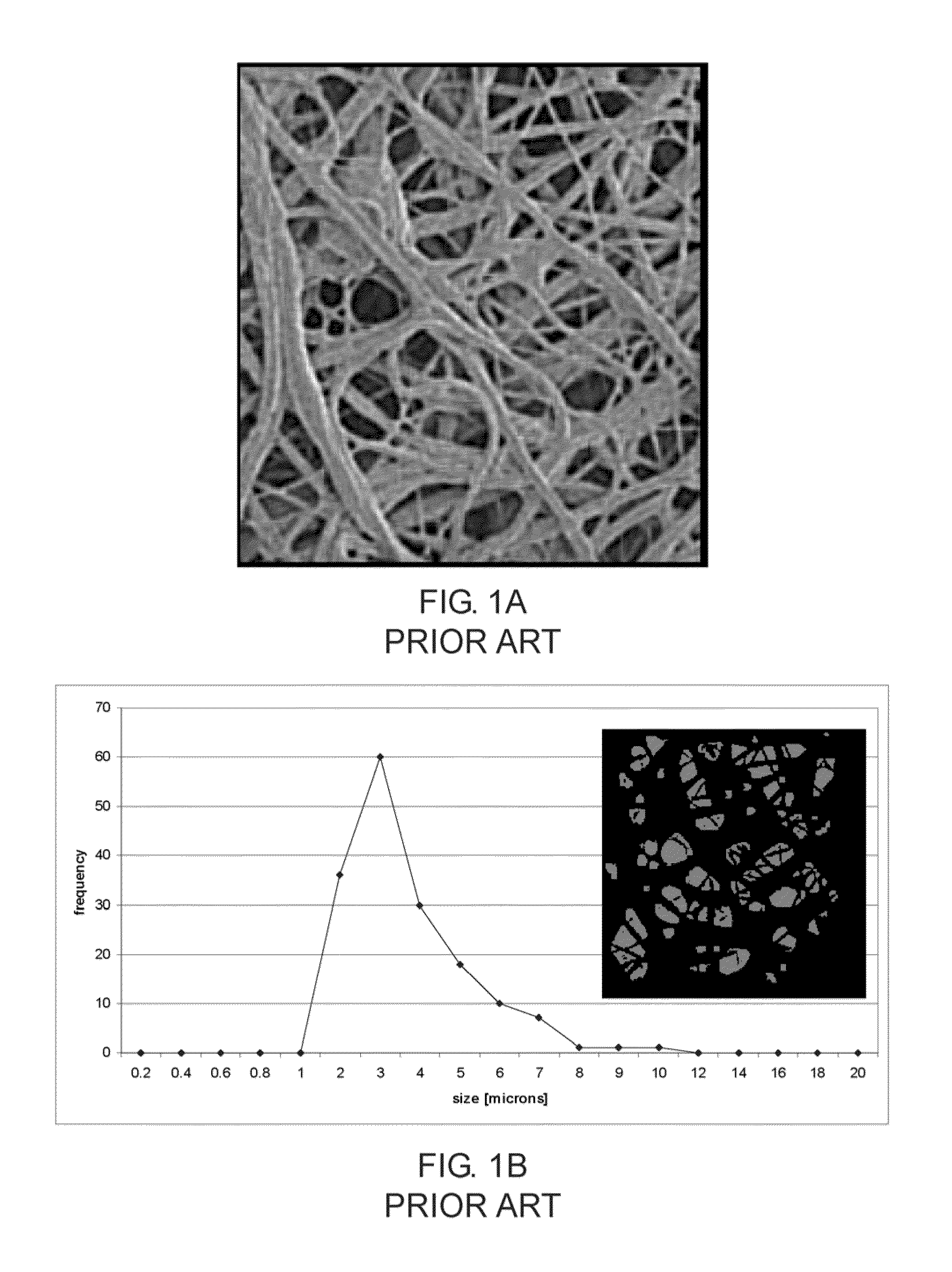
[0082]After formation of the membrane the covered stents were inspected under a digital microscope. FIG. 12A and FIG. 12B are micrographs of a portion of a stent visualizing the micro porous structure of the fibrous layer. In FIG. 12C a portion of the fibrous layer covered stent is depicted in more detail. The surface is visualized by scanning electron microscopy (SEM) at a magnification of 1500×. Nanofibers are visible. The nano-micro features including a plurality of small pores are clearly visible on the entire surface of the stent. The size of the features was determined using an image analysis technique. FIG. 12D shows a binary image computed from the micrograph of FIG. 12C and a chart showing the size of the surface features. The feature size ranges between 200 nm and 4 m...


PUM

PropertyMeasurementUnit
Lengthaaaaaaaaaa
Lengthaaaaaaaaaa
Lengthaaaaaaaaaa

Abstract

The present invention relates to biocompatible non-woven fibrous materials having a nano-micro topography and methods for producing such materials. The materials may be used to cover implantable medical devices and to fabricate a three-dimensional drug-eluting fibrous matrix featuring accurate spatial positioning of the drug particles within the matrix.

Description

CROSS-REFERENCE TO RELATED APPLICATIONS[0001]This Application relates to and claims priority from U.S. 61 / 060,106 filed Jun. 9, 2008, which is incorporated as reference herein.FEDERALLY SPONSORED RESEARCH[0002]Not ApplicableSEQUENCE LISTING OR PROGRAM[0003]Not ApplicableBACKGROUND OF THE INVENTION[0004]The present invention relates to biocompatible non-woven fibrous materials having a nano-micro topography, which may be used to cover implantable medical devices and to fabricate three-dimensional drug-eluting materials, and methods for producing such materials.[0005]Non-woven materials made from synthetic or natural polymers are used in various applications, including tissue engineering, clinical diagnostics, wound healing, drug delivery, and medical implants. Such materials may be employed, among others, to produce vascular grafts for supporting a weakened artery and covered stents which inhibit tissue growth into the stents. Vascular grafts and covered stents generally consist of a...

Claims


Application Information

Patent Timeline
IPC IPC(8): A61F2/00B05D3/00B05D1/02C12N11/10A61F2/04A61K9/70A61L33/00A61F2/02C12N11/08
CPCA61L27/507D01D5/14A61L27/18A61L27/26A61L27/34A61L27/38A61L27/54A61L27/58A61L31/10A61L31/148A61L31/16A61L27/16D01D5/0084D01D5/0038D04H1/732D04H1/724B05B13/0235B05B1/341C08L67/04C08L31/04C08L75/04C08L71/02A61L2400/12A61L2420/02A61L2420/06A61L2420/08D01D5/0069
Inventor SCHEER, INGOBEAUMONT, CLAUDIA
Owner SCHEER INGO
Why Eureka
Try Eureka