
Thermoelectric converter and method of manufacturing same

a technology of thermoelectric converter and manufacturing method, which is applied in the manufacture/treatment of thermoelectric devices, transportation and packaging, and thermoelectric devices. it can solve the problems of insufficient reduction of thermal conductivity, inability to disperse metals or alloys into thermoelectric conversion materials in the nanomicron order, and inability to increase the performance of thermoelectric conversion materials. it achieves the effect of increasing electrical conductivity and reducing thermal conductivity

Inactive Publication Date: 2013-03-12
TOYOTA JIDOSHA KK
View PDF32 Cites 11 Cited by
  • Summary
  • Abstract
  • Description
  • Claims
  • Application Information

AI Technical Summary

Benefits of technology

The present invention relates to a thermoelectric conversion material with improved performance. The material has a high output factor and low thermal conductivity, which can be achieved by controlling the size of the material and the thermal conductivity of the matrix. The invention also involves the use of metal or alloy particles dispersed in the material, which can decrease thermal conductivity at the boundary between the metal and the matrix. The method of manufacturing the material involves depositing particles of the material and a salt of the metal or alloy in a solution, followed by heat treatment to form a dispersion phase of the metal or alloy in the material. The invention can be used in the manufacturing of thermoelectric converters with high efficiency.

Problems solved by technology

However, in a conventional conversion material in which the inactive fine particles are unevenly distributed, the inactive fine particles, which provide the scattering effect of the phonons, have a large adverse influence on the other physical properties, such as electrical resistivity, due to the uneven distribution thereof, thus an increase in the performance of the thermoelectric conversion materials is inhibited.
However, the metals or alloys as the dispersant have a particle size of submicron to a few hundreds micron order and therefore, it is impossible to disperse the metals or alloys into the thermoelectric conversion material in the nanomicron order.
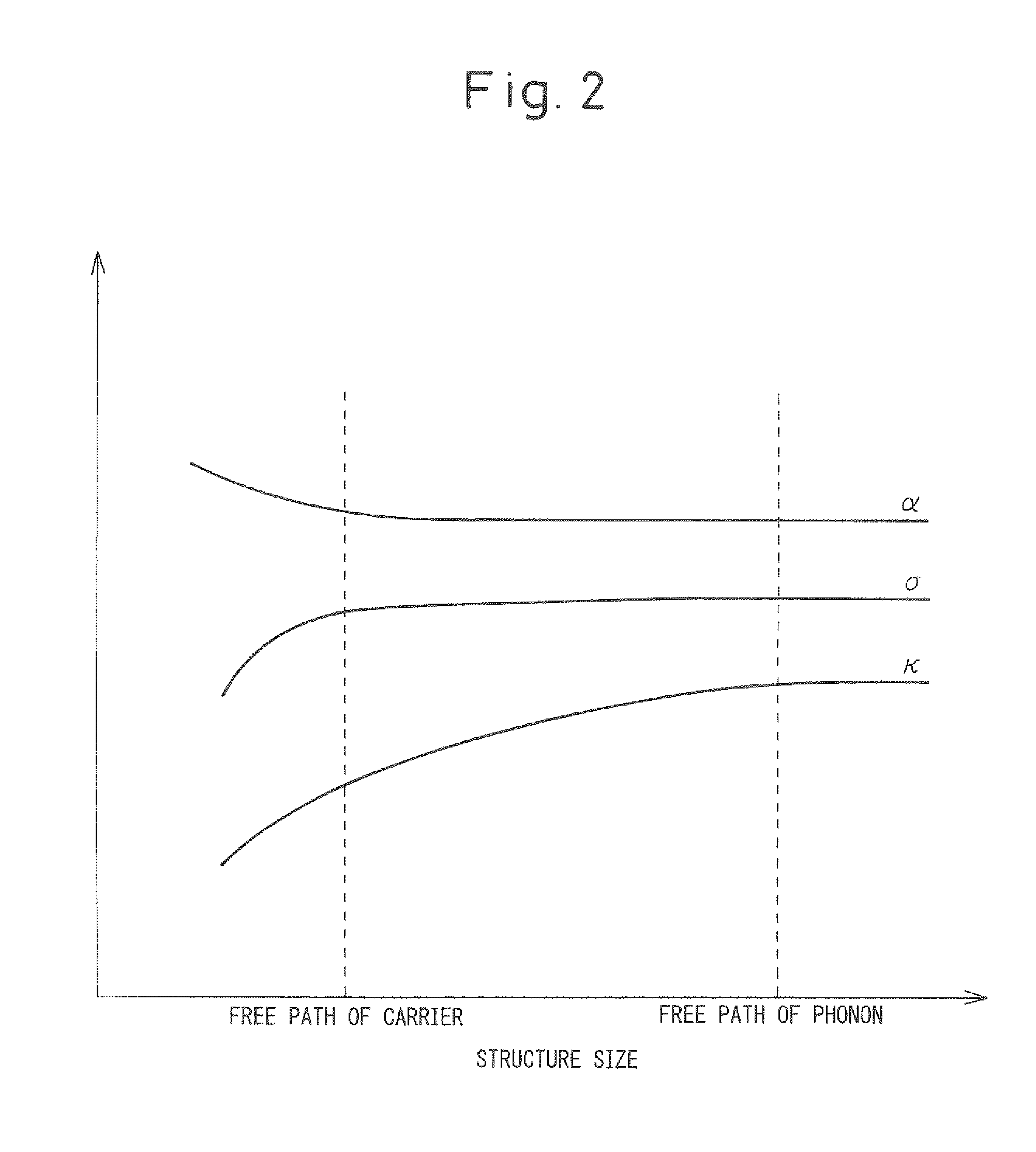
Further, grain-growth of the metals or alloys may occur during sintering, as a result, the distance between the metals is larger than the mean free path of the phonons of the thermoelectric conversion material, and consequently thermal conductivity cannot be sufficiently reduced.

Method used


Image

  • Thermoelectric converter and method of manufacturing same
  • Thermoelectric converter and method of manufacturing same
  • Thermoelectric converter and method of manufacturing same

Examples


example

Example 1

[0058]2.0 g of sodium borohydride as a reducing agent was mixed in 100 mL of ethanol. On the other hand, 0.9 g of cobalt chloride, 3.6 g of antimony chloride, and 0.18 g of nickel chloride were mixed in 100 mL of ethanol, and the solution was dropped into the above sodium borohydride solution. Cobalt, antimony, and nickel particles formed thereby, were rinsed with a mixed solution of ethanol and water (mixing ratio 1:1), and impurities were removed.

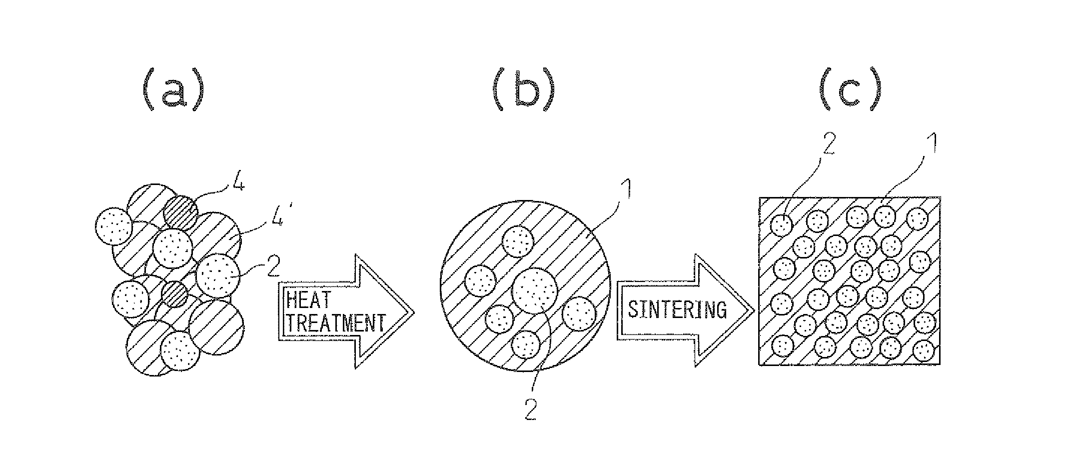
[0059]The resulting slurry comprising the cobalt, antimony, and nickel was hydrothermally treated at 240° C. for 24 hours. Consequently, NiSb was deposited in the thermoelectric conversion material due to an excess amount of nickel and antimony which exceed the solid dissolution limit of the aimed thermoelectric conversion material Co0.9Ni0.1Sb3. After that, the thermoelectric converter of the present invention was obtained by SPS sintering at 500° C. The TEM image of the thermoelectric converter is shown in FIG. 5. The NiSb phas...

example 2

[0063]0.7 g of sodium borohydride as a reducing agent was mixed with 100 mL of ethanol. On the other hand, 0.8 g of nickel chloride, and 0.77 g of antimony chloride were mixed with 100 mL of ethanol, and the solution was dropped into the above sodium borohydride solution. Thus, particles of nickel antimony were produced, hydrothermally treated at 240° C. for 24 hours, and NiSb alloy particles having an average particle size of 10 to 20 nm were obtained. 0.6 g of the NiSb alloy particles were added to 100 mL of ethanol, and 1.7 g of sodium borohydride was further added.

[0064]0.9 g of cobalt chloride, 2.7 g of antimony chloride, and 0.057 g of nickel chloride were mixed with 100 mL of ethanol, and the solution was dropped into the above ethanol solution comprising NiSb alloy. Thus, particles of Co, Ni, and Sb were deposited around the NiSb alloy particles. Then, hydrothermal treatment at 240° C. for 24 hours was performed to obtain composite particles coated with the thermoelectric co...


PUM

PropertyMeasurementUnit
particle sizeaaaaaaaaaa
distanceaaaaaaaaaa
distanceaaaaaaaaaa

Abstract

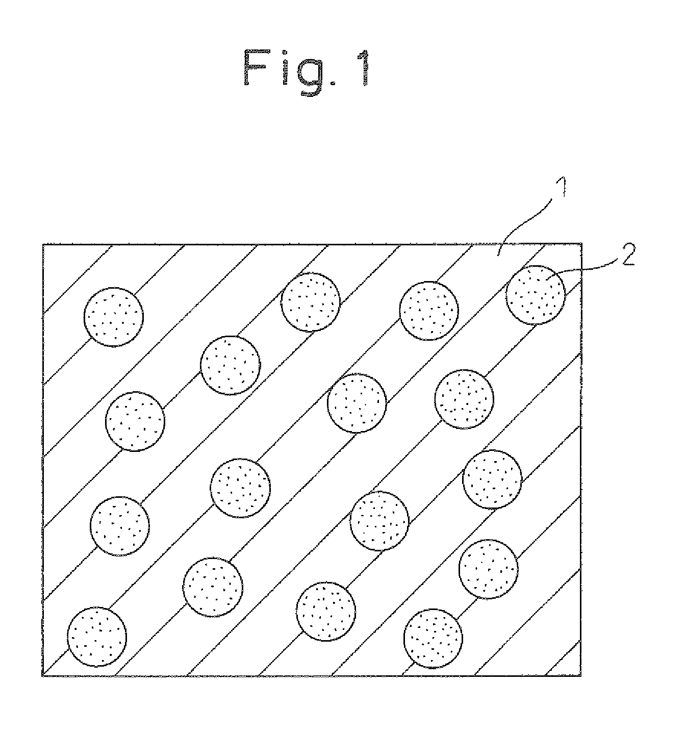
A thermoelectric converter made of a thermoelectric conversion material is provided in which metal or alloy particles having an average particle size of 1 to 100 nm are dispersed, wherein at least a part of the metal or alloy particles are dispersed at a distance not more than the mean free path of the phonon of the thermoelectric conversion material.

Description

CROSS-REFERENCE TO RELATED APPLICATIONS[0001]This application is a national phase application of International Application No. PCT / JP2008 / 060244, filed May 28, 2008, and claims the priority of Japanese Application No. 2007-150729, filed Jun. 6, 2007, the contents of both of which are incorporated herein by reference.FIELD OF THE INVENTION[0002]The present invention relates to a thermoelectric converter comprising metal or alloy particles, and a method of manufacturing the same.BACKGROUND ART[0003]A thermoelectric conversion material is a material which can interconvert thermal and electric energies, and constitutes a thermoelectric converter which is used as a thermoelectric cooling element or a thermoelectric power generating element. Thermoelectric conversion material is used for thermoelectric conversion using the Seebeck effect. Thermoelectric converting performance is represented by Formula (1) which is called the performance index ZT.ZT=α2σT / κ  (1)(wherein, α represents Seebec...

Claims


Application Information

Patent Timeline
Patent Type & Authority Patents(United States)
IPC IPC(8): H01L35/26C22C12/00H01L35/18B22F1/02B22F9/24H01L35/34B22F1/17
CPCB22F1/025B22F9/24C22C12/00C22C18/00C22C23/00H01L35/18H01L35/26H01L35/34B22F2998/00B22F1/0018B22F1/0044B22F1/17H10N10/857H10N10/853H10N10/01B22F1/07B22F1/054
Inventor MURAI, JUNYAKITA, TAKUJI
Owner TOYOTA JIDOSHA KK
Learn More