
Process to C-manufacture acrylonitrile and hydrogen cyanide

a technology of acrylonitrile and hydrogen cyanide, which is applied in the direction of hydrogen cyanide preparation/purification/separation, separation processes, organic chemistry, etc., can solve the problems of unfavorable hcn polymerization, polymer formation and fouling in downstream equipment, and more frequent catalyst replacement, so as to achieve the reduction of the relative weight ratio of acrylonitrile to hydrogen cyanide and the effect of substantially preventing hcn

Active Publication Date: 2013-11-19
THE CHEMOURS CO FC LLC
View PDF35 Cites 9 Cited by
  • Summary
  • Abstract
  • Description
  • Claims
  • Application Information

AI Technical Summary

Benefits of technology

The present invention is a process for simultaneously manufacturing acrylonitrile and hydrogen cyanide. The process involves combining the two product streams and treating them in a recovery column, a decanter, and a heads column to control the pH. The ratio of acrylonitrile to hydrogen cyanide in the combined product stream is controlled by adjusting the feed rate of the hydrogen cyanide stream. The process allows for greater recovery of hydrogen cyanide relative to a conventional process. The combination of processes in a single recovery / purification operation is safe and efficient, without the need for a separate purification system.

Problems solved by technology

High heat released at the catalyst surface as methanol reacts leads to catalyst deactivation resulting in more frequent catalyst replacement.
Methanol can also react with ammoxidation intermediates to form reactive intermediates that can lead to polymer formation and fouling in downstream equipment.
Methanol also reacts with oxygen in the system, consuming this reagent, and forming undesired by-products, such as carbon oxides.
Less obvious disadvantages of methanol injection process are increased cost for equipment and energy due to the need to convert methane to methanol.
HCN is a highly toxic and flammable gas.
At high concentrations, risk increases for exothermic runaway reaction through polymerization and decomposition, which is a potentially explosive situation.
High concentrations of HCN in acrylonitrile systems are relatively unstable, and solid polymeric HCN can form in the heads column, reducing column pressure.
Solid polymerization products plug equipment, such as relief systems, valves, instruments, and piping, which in turn, increase risks associated with HCN.
Downtime associated with cleaning of the solids and other downstream process equipped is increased and results in substantial costs and loss production of ACRN and HCN.

Method used


Image

  • Process to C-manufacture acrylonitrile and hydrogen cyanide
  • Process to C-manufacture acrylonitrile and hydrogen cyanide

Examples


examples

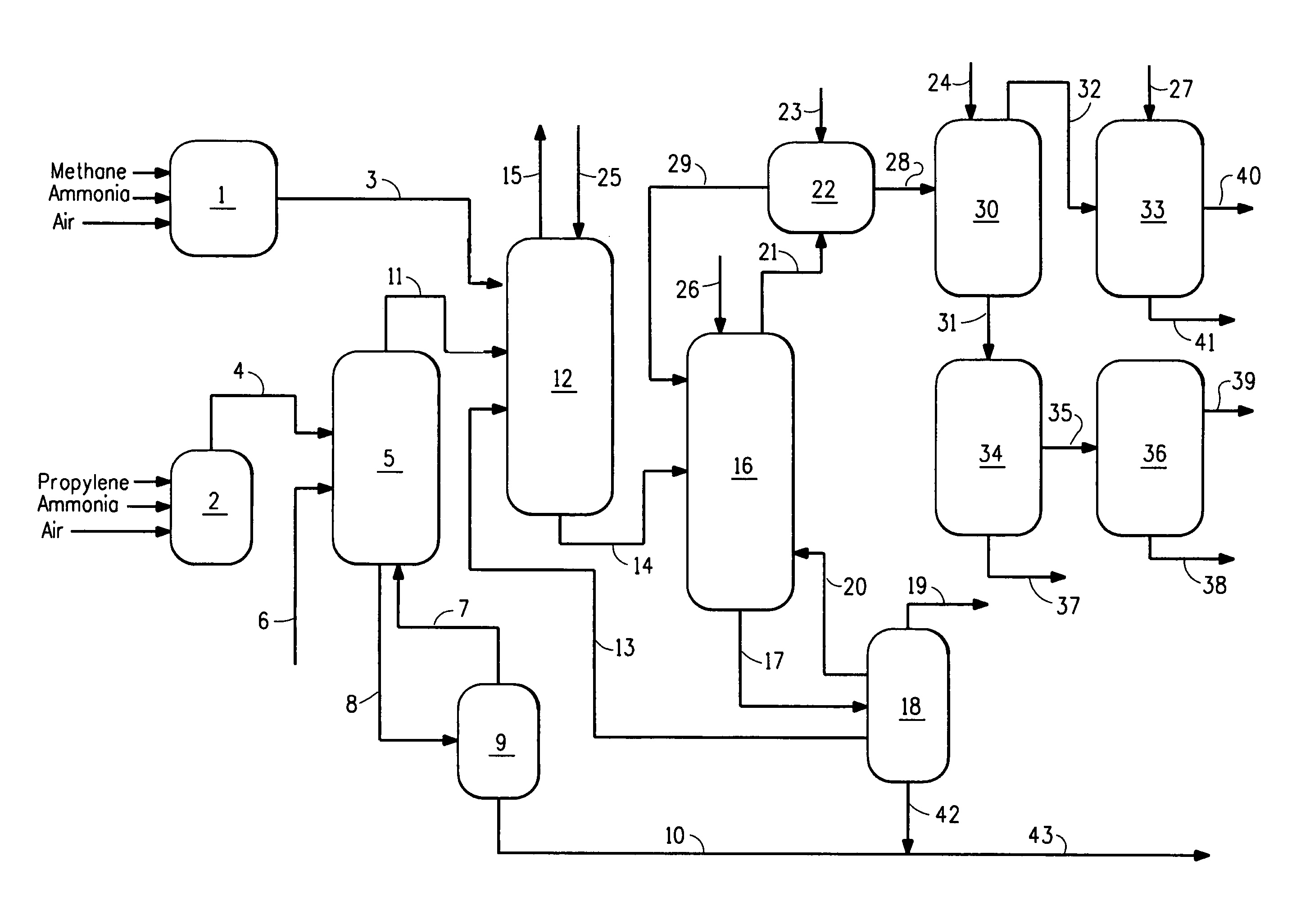
[0052]The following Examples were performed in a flow system as illustrated in FIG. 1. For the Comparative Example, there was no HCN synthesis reactor and no HCN product stream present. The ACRN product stream (reactor effluent from acrylonitrile synthesis reactor) was treated in a quench column to reduce temperature to 46° C. and then fed to an absorber column. The HCN product stream (in Examples 1 and 2 only) was similarly quenched to a temperature of about 55° C. was combined with the ACRN product stream in the absorber column. The product stream (ACRN or combined stream) passed from the absorber column to a recovery column to a decanter, wherein an aqueous layer was separated from an organic layer, with the aqueous layer recycled to the recovery column and the organic layer fed to a heads column where crude HCN was separated from crude ACRN. Crude ACRN was removed from the bottom of the heads column and sent to a drying column and then further purification and packaging. Crude H...

example 1

[0056]The process of the Comparative Example was repeated, with the following changes. A hydrogen cyanide reactor was operated producing an HCN product stream, which was combined with quenched stream from the ACRN process in the ACRN recovery / purification system used in the Comparative Example and as described above. ACRN was produced at the same rate as was produced in the Comparative Example. The amount of HCN produced from the ACRN reactor and hydrogen cyanide reactor was about 2.5 times the amount produced in Comparative Example.

[0057]High concentration of HCN in the streams, especially in the recovery column and decanter provide greatest concern for safety, where there are high concentrations of HCN in organic phases, susceptible to polymerization. In this Example 1, the pH was monitored and controlled at the absorber column, recovery column, decanter, heads column, and drying column by adding glycolic acid to the column or decanter, as needed to stabilize against polymerizatio...

example 2

[0060]The process of Example 1 was repeated, but the amount of HCN produced was varied to provide ratios of ACRN to HCN of 2 to 1, 4 to 1 and 5 to 1 to show the ability to vary rate of co-manufacture of HCN and ACRN. In this Example, the pH was monitored and controlled at the absorber column, recovery column, decanter, heads column, and drying column by adding glycolic acid to the column or decanter, as needed to stabilize against polymerization. Thus, the process of this invention can provide varying amounts of HCN relative to ACRN with minimal need for added investment in recovery and purification operations. Polymerization of HCN was substantially prevented.


PUM

PropertyMeasurementUnit
pHaaaaaaaaaa
weight ratioaaaaaaaaaa
pHaaaaaaaaaa

Abstract

A process for co-manufacture of acrylonitrile and hydrogen cyanide comprises combining a stream comprising hydrogen cyanide and an acrylonitrile reactor product stream, to produce a combined product stream, having a ratio of acrylonitrile to hydrogen cyanide of about 9 to 1 or less, which can be varied; and treating the combined product stream in a recovery / purification system of acrylonitrile process wherein pH is controlled by addition of an acid to prevent HCN polymerization. The ratio of acrylonitrile to hydrogen cyanide is generally between 2 to 1 and 9 to 1. The stream comprising hydrogen cyanide is advantageously a hydrogen cyanide product stream from a hydrogen cyanide synthesis reactor.

Description

FIELD OF THE INVENTION[0001]This invention relates to a process for the co-manufacture of acrylonitrile and hydrogen cyanide with improved control and efficiency.BACKGROUND OF THE INVENTION[0002]Acrylonitrile (ACRN) is an important monomer for the synthesis of various polymers including acrylic fibers, synthetic rubbers, nylons, and is the starting material for acrylic acids and acrylaminde. Processes to prepare acrylonitrile are well known, and include the so-called “Sohio Process” in which propylene / propane react with ammonia and oxygen (air) over a catalyst at elevated temperatures (“ammoxidation”). Hydrogen cyanide (HCN) and acetonitrile (CH3CN) are produced as by-products.[0003]HCN is a valuable by-product due to it vast uses as a starting material or as an intermediate. HCN is used, for example, as a starting material for the synthesis of various polymers, including polyamides, and chemicals. HCN is the starting material for metal cyanides including sodium cyanide and potassiu...

Claims


Application Information

Patent Timeline
Patent Type & Authority Patents(United States)
IPC IPC(8): B01D3/34
CPCC07C253/34C07C255/08Y02P20/582C01C1/242C01C3/0212C01C3/02C07C253/00
Inventor BASHAM, BRENT E.STIMEK, RICHARD THOMAS
Owner THE CHEMOURS CO FC LLC
Learn More