Composite material bone implant

a bone implant and composite material technology, applied in the direction of osteosynthesis devices, prostheses, ligaments, etc., can solve the problems of bone deterioration and resorption, stress shielding, and a relative high degree of stress

Active Publication Date: 2014-04-29
CARBOFIX ORTHOPEDICS
View PDF94 Cites 42 Cited by
  • Summary
  • Abstract
  • Description
  • Claims
  • Application Information

AI Technical Summary

Benefits of technology

[0051]a metal exterior surface on the core. Optionally, the metal exterior surface is a plating having a smooth surface which does not promote integration with surrounding bone tissue when the screw has been implanted. Optionally or alternatively, the metal surface is comprised of titanium or a titanium alloy. Optionally or alternatively, the metal surface is thin enough that it does not cause artifacts in CT or MRI images that would interfere significantly with visualization. Optionally or alternatively, the metal surface is threaded.
[0061]a cover configured to be received in the bore after the implant is in place to prevent bone or other tissue regrowth in the bore.
[0082]cooling the bent bone nail in a manner which allows it to retain its bent shape without substantial change in its other properties.

Problems solved by technology

However, the rigid metal implant creates a relative high degree of stresses in certain regions of the bone, while, on the other hand, does not provide for sufficient load transfer resulting in stress shielding.
Both high stress and stress shielding can cause bone deterioration and resorption, leading to areas of bone weakness and loss of bone support for the implant (e.g., intramedullary nails and stem components of joint replacement systems).
In addition, metals may result in artifacts in CT and MR imaging.
Furthermore, metals such as stainless steel and cobalt chromium may cause biocompatibility problems related to corrosion and sensitization reaction (mainly due to allergy to nickel).
Although composite material implants can provide several advantages, they also have a few limitations.
In contrast to metal, composite material implants are not visible under imaging devices (such as fluoroscopy), and hence their implantation as well as tracking during follow-up are difficult.
The use of interlocking screws poses a problem in such implants, as the designated holes at the nail ends (or at the plate), through which the screws are to be introduced, are not visible under fluoroscopy.
The addition of fibers made of material that absorbs X-rays may be insufficient; as such fibers often do not adequately and accurately mark the hole.
In addition, with regards to intramedullary nails (or other implant construction that may comprise a weakened area), due to the composite material construction, the extremities of the nails at the area of the interlocking screw holes are more prone to damage.
Further, although such composite materials may have several properties that are claimed to be similar to those of bone, the composite material construction may be less efficient under torsion loads.
However, the composite material construction (which is not isotropic as is metal), has less resistance to shear forces, and damage (e.g., breakage) may result at the thread area.

Method used


Image

  • Composite material bone implant
  • Composite material bone implant
  • Composite material bone implant

Examples


Embodiment Construction

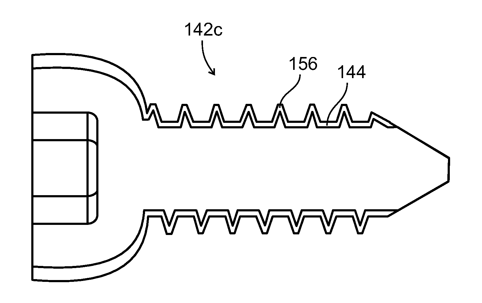
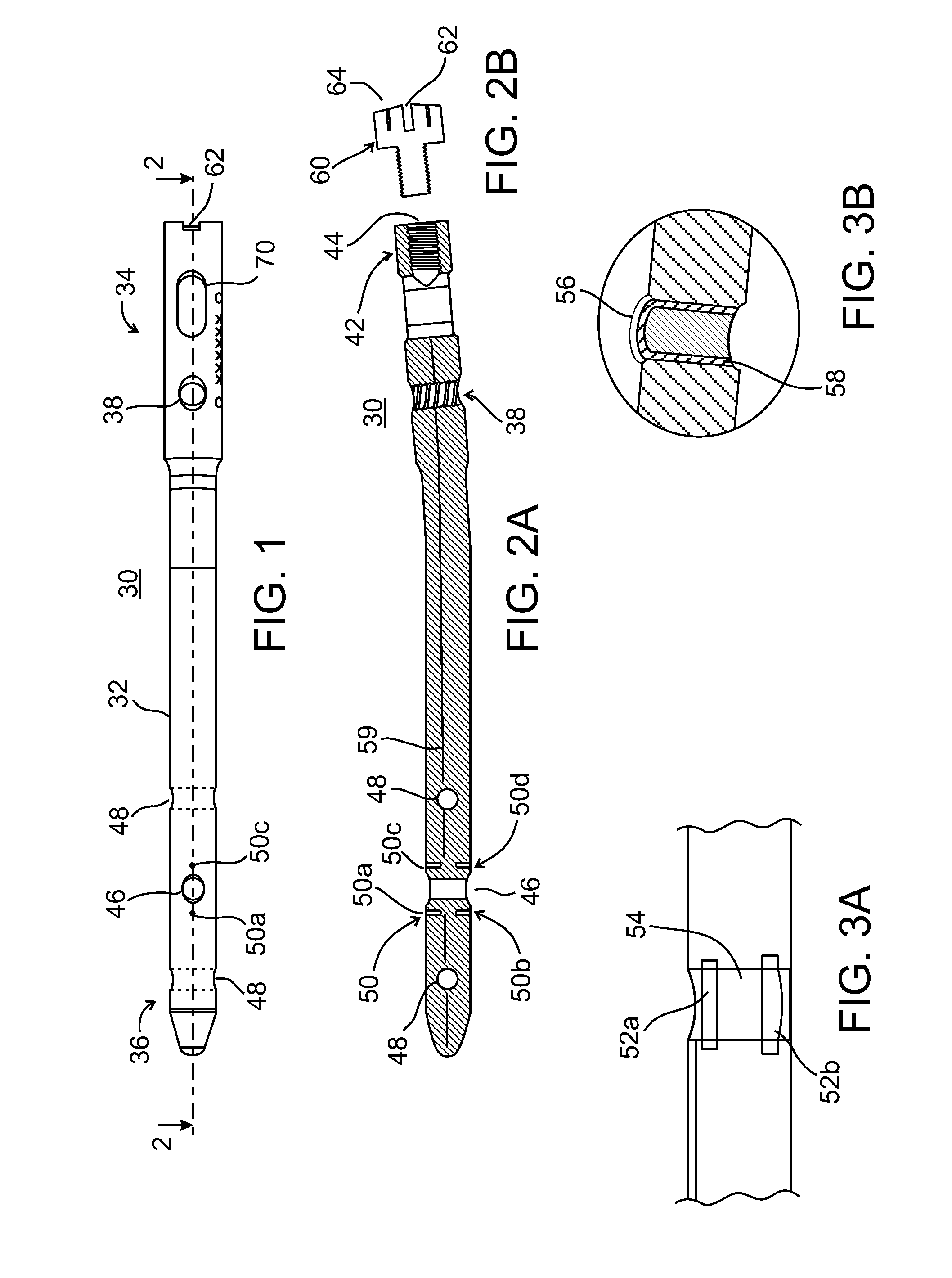
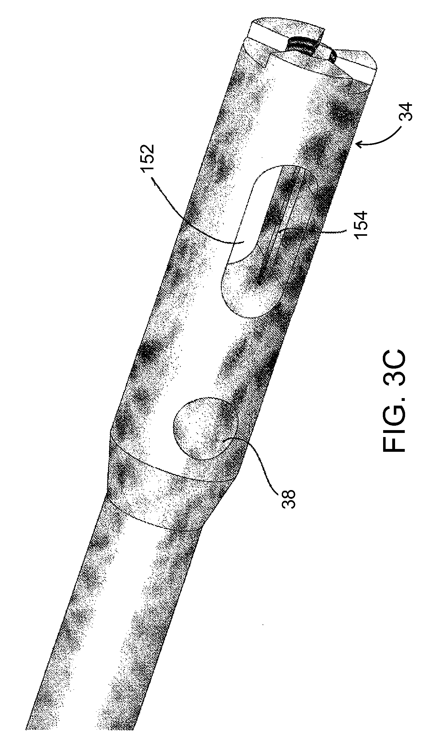
[0110]The present invention, in some embodiments thereof, relates to composite material bone implant devices and to manufacturing methods for such devices. More particularly, but not exclusively, the invention relates to such devices and methods as applied to implant devices formed of fiber-reinforced polymer matrices or self-reinforcing polymers.

[0111]According to an aspect of some embodiments of the invention, implants are formed of a matrix of polymer material such as polyarylether ketone (PAEK), polyether ether ketone (PEEK), or other polyketone based polymers. Implants according to some embodiments of the invention may also be formed of a matrix polymer material such as but not limited to polyphenylene, polyphenylsulfone, or polysulfone. In all such embodiments, reinforcing fibers may included in the matrix. Optionally, these may be formed of carbon, ultrahigh density polyethylene (UHDPE), aramid polymers, or ceramic fibers such as glass. Optionally, two or more of these may be...


PUM


Abstract

A composite bone implant. In some embodiments, one or more features are provided, such as markers for passageways, axial engagement of bone screws, sliding support of bone screws and / or a cannulated channel for a guide wire.

Description

RELATED APPLICATIONS[0001]This application is a National Phase of PCT Patent Application No. PCT / IB2010 / 050225 having International filing date of Jan. 18, 2010, which claims the benefit of priority of U.S. Provisional Patent Application Nos. 61 / 213,991 filed on Aug. 6, 2009 and 61 / 205,160 filed on Jan. 16, 2009. The contents of the above applications are all incorporated herein by reference.FIELD OF INVENTION[0002]The present invention in some embodiments thereof, relates to composite material bone implant devices and to manufacturing methods for such devices.[0003]As used herein, the terms “bone implant devices” and “bone implants” are intended to encompass hip joints, knee joints, shoulder joints, bone screws, bone instruments, bone plates, and intramedullary nails, including proximal femur nails, typically including screw holes for receiving bone fixation screws.BACKGROUND OF THE INVENTION[0004]Intramedullary nails (bone nails) have become a treatment of choice for the fixation ...

Claims


Application Information

Patent Timeline
Patent Type & Authority Patents(United States)
IPC IPC(8): A61B17/84
CPCA61B17/8872A61B17/8052A61B17/1725A61B17/866A61B17/7208A61B19/54A61B2017/00831A61B17/80A61B17/8625A61B17/92A61B17/7241A61B17/744A61B17/864A61B17/7225A61B17/72A61B17/1631A61B17/1655A61B17/725A61B17/74A61B17/8685A61B90/39A61B17/16A61B17/1615A61B17/1628A61B17/746A61B2090/3966A61B17/7233
Inventor BEYAR, MORDECHAYGLOBERMAN, ORENEINAV, ELADWACHSLER-AVRAHAMI, HILA
Owner CARBOFIX ORTHOPEDICS
Why Eureka
Try Eureka