Multi-mode fiber amplifier

a fiber amplifier and multi-mode technology, applied in the direction of optical resonator shape and construction, electromagnetic transmission, transmission, etc., can solve the problems of modal dispersion, the most detrimental effect of diffraction-limited coherent light generation, and the early work on fiber lasers that did not attract considerable attention. , to achieve the effect of increasing the energy storage potential of an optical fiber amplifier

Inactive Publication Date: 2014-06-24
IMRA AMERICA
View PDF288 Cites 10 Cited by
  • Summary
  • Abstract
  • Description
  • Claims
  • Application Information

AI Technical Summary

Benefits of technology

[0028]It is an object of the present invention to increase the energy storage potential in an optical fiber amplifier and to produce peak powers and pulse energies which are higher than those achievable in single-mode (SM) fibers before the onset of undesirable nonlinearities and gain saturation.
[0029]Another object of the present invention is to achieve amplification of the fundamental mode within a multi-mode (MM) fiber while reducing amplified spontaneous emission (ASE).
[0030]A further object of the present invention is to employ gain-guiding within a MM fiber to improve the stability of the fundamental mode.

Problems solved by technology

However, early work on fiber lasers did not attract considerable attention, because no methods of generating diffraction-limited coherent light were known.
In general, modal dispersion is the most detrimental effect limiting the transmission bandwidth of multi-mode (MM) optical fibers, since the higher-order modes, in general, have different propagation constants.
However, in the amplification of short-optical pulses, the use of SM optical fibers is disadvantageous, cause the limited core area limits the saturation energy of the optical fiber and thus the obtainable pulse energy.
Any further increase in core diameter requires a further lowering of the NA of the fiber and results in an unacceptably high sensitivity to bend-losses.
However, in general, amplification experiments in MM optical fibers have led to non-diffraction-limited outputs as well as unacceptable pulse broadening due to modal dispersion, since the launch conditions into the MM optical fiber and mode-coupling in the MM fiber were not controlled.
In this technique, however, severe mode-coupling was a problem, as the employed MM fibers supported some 10,000 modes.
Hence, only very poor modal discrimination was obtained, resulting in poor beam quality.
Also, the system of DiGiovanni did not take into account the fact that gain-guiding induced by dopant confinement can in fact effectively guide a fundamental mode in a MM fiber.
In fact, the system of DiGiovanni et al. is not very practical, since it considers a MM signal source, which leads to a non-diffraction-limited output beam.
Further, only a single cladding was considered for the doped fiber, which is disadvantageous when trying to couple high-power semi-conductor lasers into the optical fibers.
Indeed, in SM fibers, gain-guiding is irrelevant due to the strong confinement of the fundamental mode by the wave-guide structure.
However, in MM optical fibers, the confinement of the fundamental mode by the waveguide structure becomes comparatively weaker, allowing for gain-guiding to set in.
However, this work was limited to the use of MM fibers as soliton Raman compressors in conjunction with a nonlinear spectral filtering action to clean-up the spectral profile, which may limit the overall efficiency of the system.
However, hollow-core fibers have an intrinsic transmission loss, they need to be filled with gas, and they need to be kept straight in order to minimize the transmission losses, which makes them highly impractical.
One of the limitations of this technique is that, in the compression grating, a SM fiber with a limited core area is employed.
However, Gambling et al. found low levels of mode-coupling only in liquid-core fibers.
On the other hand, mode-coupling in MM solid-core fibers was found to be severe, allowing for the propagation of a fundamental mode only in mm lengths of fiber.
The inventors are not aware of any prior art using MM fibers to amplify SM signals where the output remains primarily in the fundamental mode, the primary reason being that amplification in MM fibers is typically not suitable for long-distance signal propagation as employed in the optical telecommunication area.

Method used


Image

  • Multi-mode fiber amplifier
  • Multi-mode fiber amplifier
  • Multi-mode fiber amplifier

Examples


first embodiment

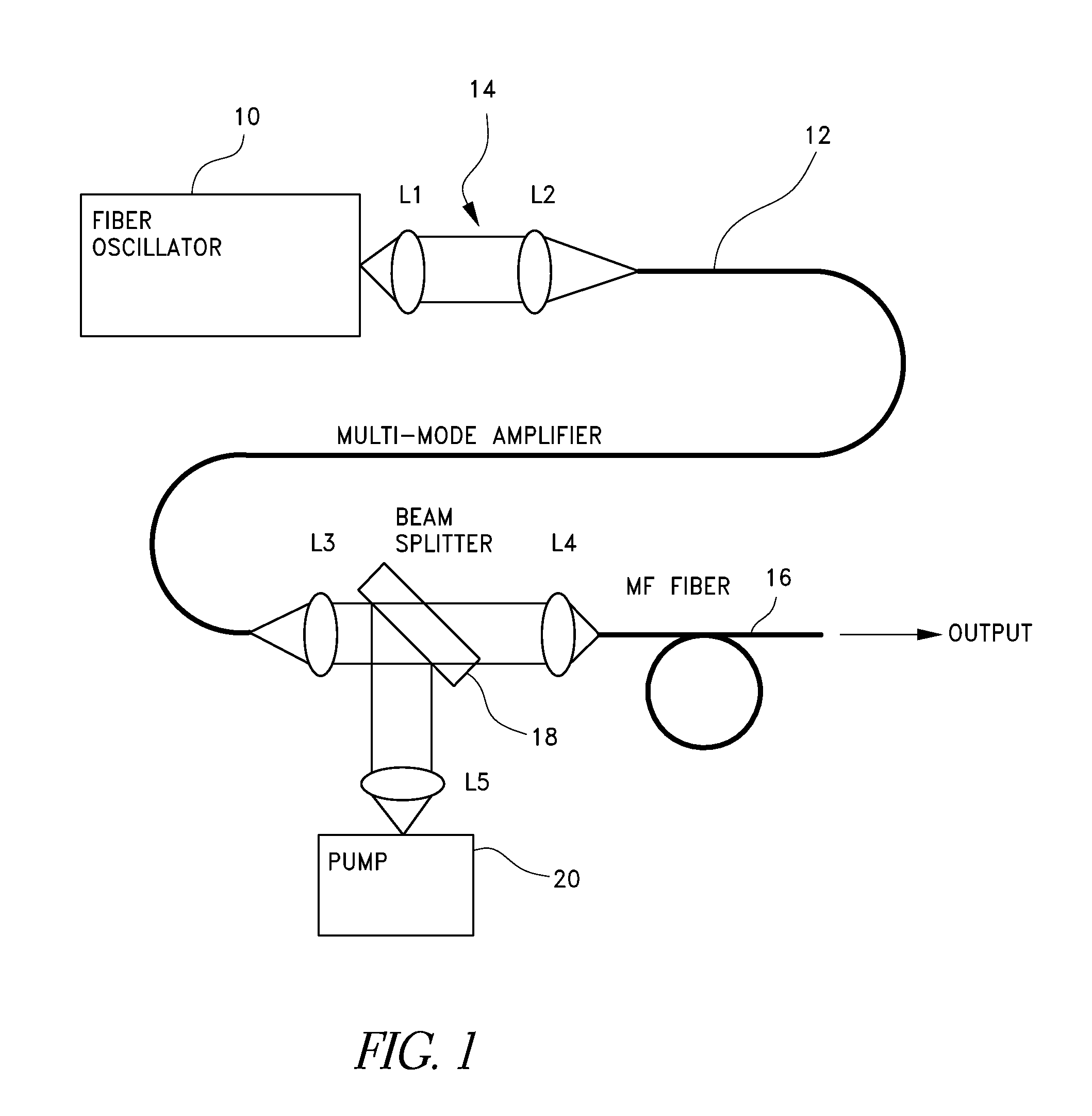
[0039]FIG. 1 illustrates an amplifier system according to the present invention. In the example shown in FIG. 1, a femtosecond single-mode (SM) fiber oscillator 10, such as an erbium fiber oscillator, is coupled into a multi-mode (MM) fiber amplifier 12, such as an erbium / ytterbium fiber amplifier. Other examples of suitable MM fiber amplifiers include those doped with Er, Yb, Nd, Tm, Pr or Ho ions. Oscillators suitable for use in this system are described in the above-mentioned U.S. patent application Ser. No. 08 / 789,995 to Fermann et al.

[0040]A two-lens telescope 14 (L1 and L2) is used to match the mode from the oscillator 10 to the fundamental mode of the MM amplifier 12. In addition, the output of the pumped MM fiber 12 is imaged into a second SM fiber (mode-filter (MF) fiber 16 in FIG. 1) using lenses L3 and L4. Lenses L3 and L5 and beamsplitter 18 are used to couple the pump light from pump source 20 into the amplifier fiber, as described below.

[0041]In one example of the syst...

second embodiment

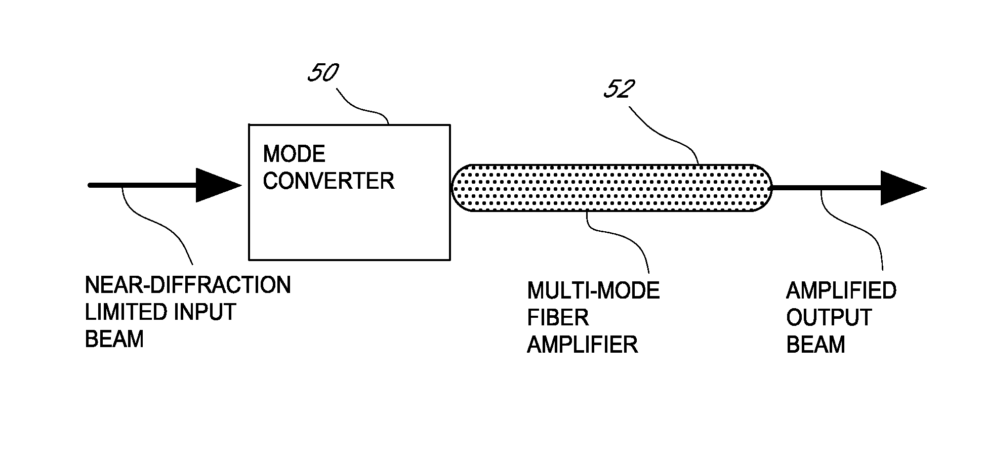
[0068]FIG. 5 is a block diagram of a multi-mode fiber amplifier system according to the present invention. The system includes a near-diffraction limited input beam, a mode-converter 50 and a MM fiber amplifier 52. The near-diffraction limited input beam can be generated from any laser system, which need not be a fiber laser. The near-diffraction limited input beam can contain cw or pulsed radiation. The mode-converter 50 can consist of any type of optical imaging system capable of matching the mode of the MM amplifier 52. For example, a lens system may be employed. Alternatively, a section of tapered fiber may be employed, such that the output mode at the end of the tapered fiber is matched to the mode of the MM amplifier fiber 52. In this case, the mode-converter can be spliced directly to the MM fiber 52 producing a very compact set-up. Any pumping configuration could be employed for the MM amplifier fiber, such as contra- or co-directional pumping with respect to the signal or s...

fourth embodiment

[0076]FIG. 7 is a diagrammatic view of a system according to the present invention. As shown in FIG. 7, a mode-filter 70 is inserted in front of one of the cavity mirrors M1 and M2 to ensure a diffraction-limited output of the system. The mode filter 70 can consist of a standard SM fiber in conjunction with appropriate mode-matching optics. Alternatively, a tapered fiber can be used (as discussed above) to provide for mode-matching. For optimum mode-coupling the efficiency of the laser will be nearly as high as for an all-SM laser. However, the use of MM amplifier 76 allows for increased design flexibility. Thus, double-clad erbium / ytterbium fibers with different core-cladding ratios can be employed wherever appropriate.


PUM


Abstract

A laser utilizes a cavity design which allows the stable generation of high peak power pulses from mode-locked multi-mode fiber lasers, greatly extending the peak power limits of conventional mode-locked single-mode fiber lasers. Mode-locking may be induced by insertion of a saturable absorber into the cavity and by inserting one or more mode-filters to ensure the oscillation of the fundamental mode in the multi-mode fiber. The probability of damage of the absorber may be minimized by the insertion of an additional semiconductor optical power limiter into the cavity.

Description

RELATED APPLICATIONS[0001]This application is a continuation application of U.S. application Ser. No. 09 / 785,944 filed Feb. 16, 2001, which is a continuation application of U.S. application Ser. No. 09 / 199,728 filed Nov. 25, 1998, now U.S. Pat. No. 6,275,512 issued Aug. 14, 2001.FIELD OF THE INVENTION[0002]The present invention relates to the amplification of single mode light pulses in multi-mode fiber amplifiers, and more particularly to the use of multi-mode amplifying fibers to increase peak pulse power in a mode-locked laser pulse source used for generating ultra-short optical pulses.BACKGROUND OF THE INVENTIONBackground Relating to Optical Amplifiers[0003]Single-mode rare-earth-doped optical fiber amplifiers have been widely used for over a decade to provide diffraction-limited optical amplification of optical pulses. Because single mode fiber amplifiers generate very low noise levels, do not induce modal dispersion, and are compatible with single mode fiber optic transmission...

Claims


Application Information

Patent Timeline
Patent Type & Authority Patents(United States)
IPC IPC(8): H01S3/11H01S3/067H01S3/08H01S3/10H01S3/098H01S3/06
CPCH01S3/06783H01S3/1115H01S3/1109H01S3/06729H01S3/06745G02B6/26H01S3/067H01S3/06716H01S3/0092H01S3/06708H01S3/06712H01S3/06725H01S3/06737H01S3/08045H01S3/094007H01S3/1106H01S3/1608H01S3/1618H01S3/08054H01S3/094042H01S3/094069H01S3/06733H01S3/094019H01S3/06704H01S3/1118
Inventor FERMANN, MARTIN E.HARTER, DONALD J.
Owner IMRA AMERICA
Why Eureka
Try Eureka