
Specialized lined landfill system for the stabilization and containment of drilling wastes and coal combustion residues

a landfill system and drilling waste technology, applied in solid waste management, climate sustainability, foundation engineering, etc., can solve the problems of pollution, novel and significant challenges to the state's waste disposal system, and primary and potentially hazardous waste streams, and achieve the effects of reducing the impact of two major waste streams on the environment, convenient placement, and compacting

Active Publication Date: 2014-08-19
MANNO JR JAMES JOSEPH +1
View PDF30 Cites 3 Cited by
  • Summary
  • Abstract
  • Description
  • Claims
  • Application Information

AI Technical Summary

Benefits of technology

This patent is about a system and method for disposing of drilling waste and coal combustion residues in a landfill. The system can sequester brine and other gas production-related contaminants with CCR. The waste products can include drill cuttings, brine solutions, heavy metal sludge, and CCR. The landfill can be designed to have zero or near-zero waste discharge and to have minimal impact on the environment. The present invention provides a safe, cost-effective, and environmentally stable method for disposing of waste from the natural gas industry and offers an opportunity for the safe and stable disposal of CCR such as fly ash, bottom ash, boiler slag, and scrubber residues. The final product can be placed, compacted, and contained in landfills. The combination of waste streams can be inserted into geotextile containers that over time become embedded in horizontal layers, resulting in a stable and environmentally effective landfill. The landfill has low permeability, zero or near-zero waste discharge, and is thus environmentally desirable and acceptable. A solidifying agent may be added to promote the solidification process.

Problems solved by technology

Drilling processes for accessing subterranean formations, including the Marcellus Shale formations, produce two primary and potentially hazardous waste streams—drill cuttings and drilling wastewater.
These waste streams resulting from the drilling process used to access the formation are presenting novel and significant challenges to the state's waste disposal systems.
Drill cuttings are generally considered to be earthen material, however, they can become polluted when they come in contact with contamination sources common to the drilling process, such as drilling fluids or drilling mud.
Once drill cuttings come into contact with synthetic drilling muds or other sources of contaminants (e.g., oils and chemical additives), then the cuttings are considered to be a contaminated soil.
Both of these disposal processes present environmental challenges and concerns.
Because of the high salt content of the Marcellus Shale formation in particular, both frac-flowback and formation / produced water are highly contaminated saltwater that requires some form of treatment before being discharged or disposed of into the local environment.
The first is dilution and release of the brine water into waterways such as rivers, however, the practice of discharging treated water into waterways is currently being phased out by the Pennsylvania Department of Environmental Protection (PADEP) because of environmental concerns.
In practice, the drilling industry finds that the chemically pre-treated water can only be reused a limited number of times in the fracturing process before it becomes necessary to dispose of the water.
Furthermore, the evaporation process generates not only clean water (which may itself be reused- / recycled for utilization in cooling towers or in the fracturing processes), but a necessary by-product is the creation of a concentrated brine solution that presents additional and unique disposal challenges.
Additionally, the first approach (i.e., to dispose of brine solution by injection into deep well sites) has a questionable future in many areas because of the limited number of injection wells currently available due to geology-related concerns as well as recent links to earthquakes generating near injection well sites.
Unfortunately, the market for beneficial salt is currently limited and insufficient to justify the significant energy requirements and capital investment required for a widespread crystallization infrastructure.
Thus, these methods do not offer a long-term solution to the problem of treating large volumes of such fluids.
Concentrated brine solutions cannot be disposed of in existing solid waste landfill systems due to its high salt concentration.
Any leakage or discharge of this highly concentrated brine would adversely affect the characteristics of generated landfill leachate by increasing its salinity.
Standard municipal landfill facility water or treatment systems are not currently designed to accept or to effectively treat brine-based water.
However, such landfills are ill-equipped to handle this sludge due to heightened environmental risks resulting from the contaminants.
In Pennsylvania, the current municipal landfills are projected to become overwhelmed in the near future as the production of gas from shale formations, and thus the waste streams associated with that production, dramatically increases.
All fly ash, however, includes substantial quantities of toxic substances.
Even though fly ash has not previously been regulated by the U.S. Environmental Protection agency (EPA) as a hazardous waste, community and environmental organizations have documented numerous environmental contamination and damage concerns arising from CCR.
Further, improperly constructed slurry impoundments, such as the one that failed in December 2008 in Kingston, Tenn., can spill onto and contaminate hundreds of acres of land and miles of waterways.
Unfortunately, as described above, there are no viable long-term solutions currently being utilized in the drilling and mining industries that provide for the environmentally acceptable and cost-effective disposal of these major waste streams produced by two major fossil fuel industries.
The environmental impact of these waste streams on states such as Pennsylvania, where the related industries are active, is reaching crisis levels.

Method used


Image

  • Specialized lined landfill system for the stabilization and containment of drilling wastes and coal combustion residues
  • Specialized lined landfill system for the stabilization and containment of drilling wastes and coal combustion residues
  • Specialized lined landfill system for the stabilization and containment of drilling wastes and coal combustion residues

Examples


examples

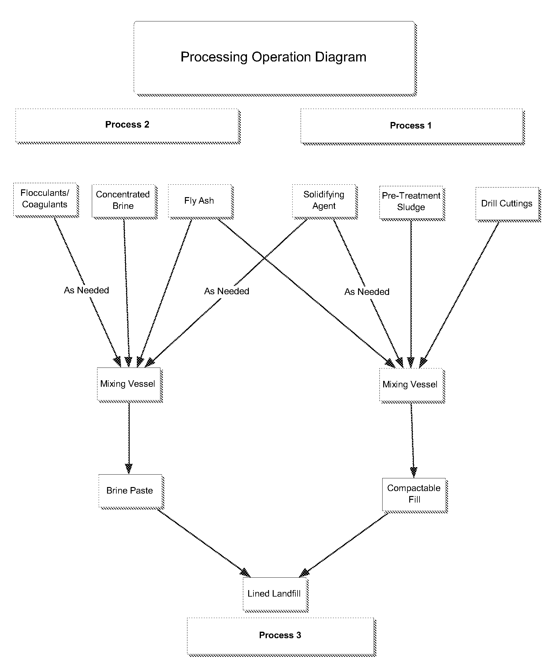
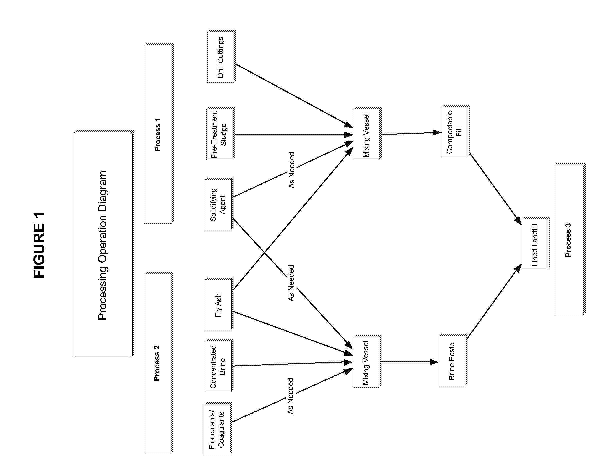
[0053]FIG. 1 shows one embodiment of the present invention. FIG. 1 includes an embodiment of Process 1, wherein drilling wastes including drill cuttings and pre-treatment sludge are combined with fly ash and solidifying agents, as needed, in a mixing vessel to make compactable fill. FIG. 1 also includes an embodiment of Process 2, wherein brine and fly ash are combined with other agents as needed in a mixing vessel to form a paste. In this embodiment, the fill and the paste are combined in a lined landfill.

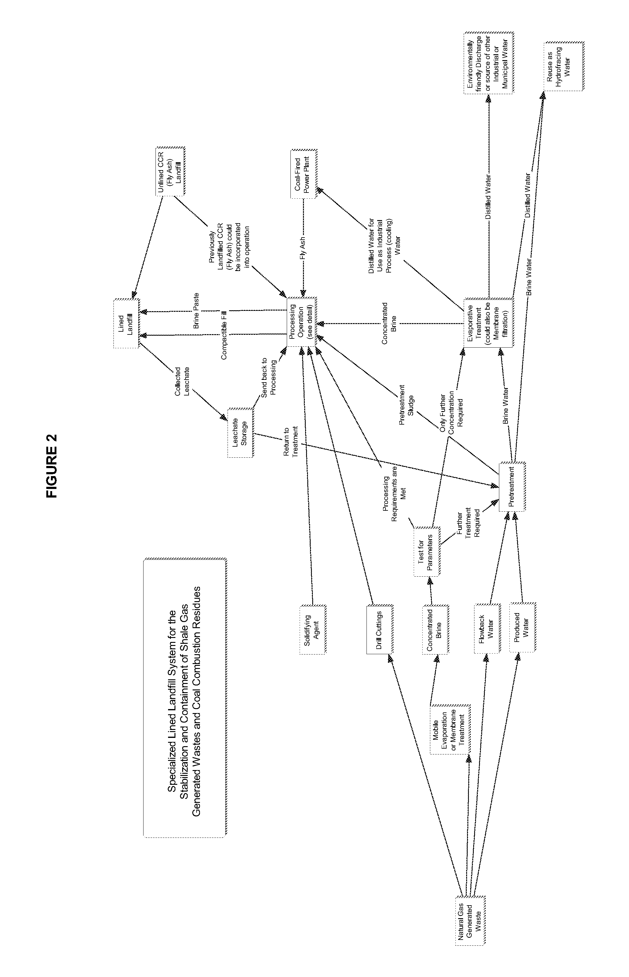
[0054]FIG. 2 shows an embodiment of a system of the present invention. A drilling site generates wastes including drilling wastewaters that are pre-treated and may be discharged or re-used as fracking water. The wastewaters may alternatively be used in Process 1 and / or 2 to form fill and / or paste. Similarly, the drill cuttings from the drilling site are used in Process 1 and / or 2. The CCR for Processes 1 and / or 2 are provided in this embodiment by a coal-fired power plant or an ex...


PUM

PropertyMeasurementUnit
depthaaaaaaaaaa
pressureaaaaaaaaaa
compositionaaaaaaaaaa

Abstract

Systems and methods of the present invention include a method for the treatment of drilling wastes and coal combustion residues, comprising combining at least a first drilling waste with coal combustion residues to form a paste, combining at least a second drilling waste with coal combustion residues to form a compactable fill, and placing the paste and the compactable fill in a landfill. Other embodiments include a method of treating drilling wastes and coal combustion residues, comprising combining at least one drilling waste with a coal combustion residue to form a paste. Further embodiments include containing the paste within at least one geotextile container. Still further embodiments include placing the geotextile container in a landfill.

Description

CROSS-REFERENCES TO RELATED APPLICATIONS[0001]This application claims the benefit under 35 U.S.C. §119(e) of the earlier filing date of U.S. Provisional Application Ser. No. 61 / 483,727 filed on May 8, 2011 and 61 / 483,057 filed on May 5, 2011 and 61 / 571,777 filed Apr. 22, 2011, the entire contents of all of these applications which are incorporated herein by reference, including any references cited therein.BACKGROUND OF THE INVENTION[0002]1. Field of the Invention[0003]The present invention relates generally to the containment of wastes from industrial processes and to the stabilization and containment of drilling wastes and coal combustion residues specifically.[0004]2. Description of the Background[0005]The extraction of fossil fuels (e.g., coal, oil, and natural gas) from subterranean geologic formations is performed extensively around the world and provides the vast majority of the world's energy resources.[0006]In the case of natural gas or oil, a small borehole is drilled from...

Claims


Application Information

Patent Timeline
Patent Type & Authority Patents(United States)
IPC IPC(8): B09B1/00B09B3/00C04B7/24C04B7/28C04B28/02C04B28/18C04B111/00
CPCC04B7/28C04B7/243C04B18/08B09B2220/06C04B28/021C04B2111/00767C04B18/06C04B28/02C04B18/10C04B18/049C04B2103/10B09B3/0041C04B22/064C04B18/0472C04B28/18E02D31/006B09C1/08E02D31/004Y02W30/91Y02W30/92Y02P40/18Y02P40/10B09B3/25B09B2101/30B09B1/00C02F1/04C02F1/44C02F2103/06C04B7/26C04B2111/00784
Inventor MANNO, JR., JAMES JOSEPHMANNO, JACQUELINE LIJA
Owner MANNO JR JAMES JOSEPH
Learn More