
Process for controlled oxidation of a ferrous solution

a technology of ferrous ions and oxidation processes, which is applied in the direction of halogen oxides/oxyacids, organic/inorganic per-compound compounding agents, manufacturing converters, etc., can solve the problem of undesirable reversed reaction of ferrous oxidation

Inactive Publication Date: 2014-10-28
BHP BILLITON OLYMPIC DAM CORP
View PDF4 Cites 0 Cited by
  • Summary
  • Abstract
  • Description
  • Claims
  • Application Information

AI Technical Summary

Benefits of technology

This patent is about a process for controlling the oxidation of ferrous sulfate in a solution using sulfur dioxide and oxygen. The inventor found that by controlling the rate of delivery of sulfur dioxide and the concentration of dissolved oxygen, the oxidation reaction can be effectively controlled regardless of changes in reactor design and other process conditions. The purity of the sulfur dioxide and oxygen can affect the rate of oxidation, so it is important to use high purity gases for certain oxidation rates and temperatures. The process can be operated at different locations by adjusting the oxygen delivery rate. The process can also be used to produce oxidizing solutions for leaching ore tailings. Thickening the leached slurry and recycling it to the leach reactor as diluent can help control the solids concentration and facilitate the diffusion of oxygen within the slurry.

Problems solved by technology

However, if the amount of SO2 is too high relative to O2 the ferrous oxidation reaction is undesirably reversed and ferric ions are reduced to ferrous ions.
The inventor has recognised that this approach is problematical because the reactions take place in the aqueous phase and the rate of diffusion between the introduced gases and the liquor is dependent on a number of factors, such as:the partial pressure of oxygen in the gas;the configuration of the reactor in which the oxidation process takes place, in particular its height (that is the hydrostatic pressure within the reactor);the degree of agitation of the ferrous solution within the reactor, in particular the type of agitator used and its power; andthe rate of utilisation of the dissolved oxygen in solution by chemical reaction.

Method used


Image

  • Process for controlled oxidation of a ferrous solution
  • Process for controlled oxidation of a ferrous solution
  • Process for controlled oxidation of a ferrous solution

Examples


examples 1 to 4

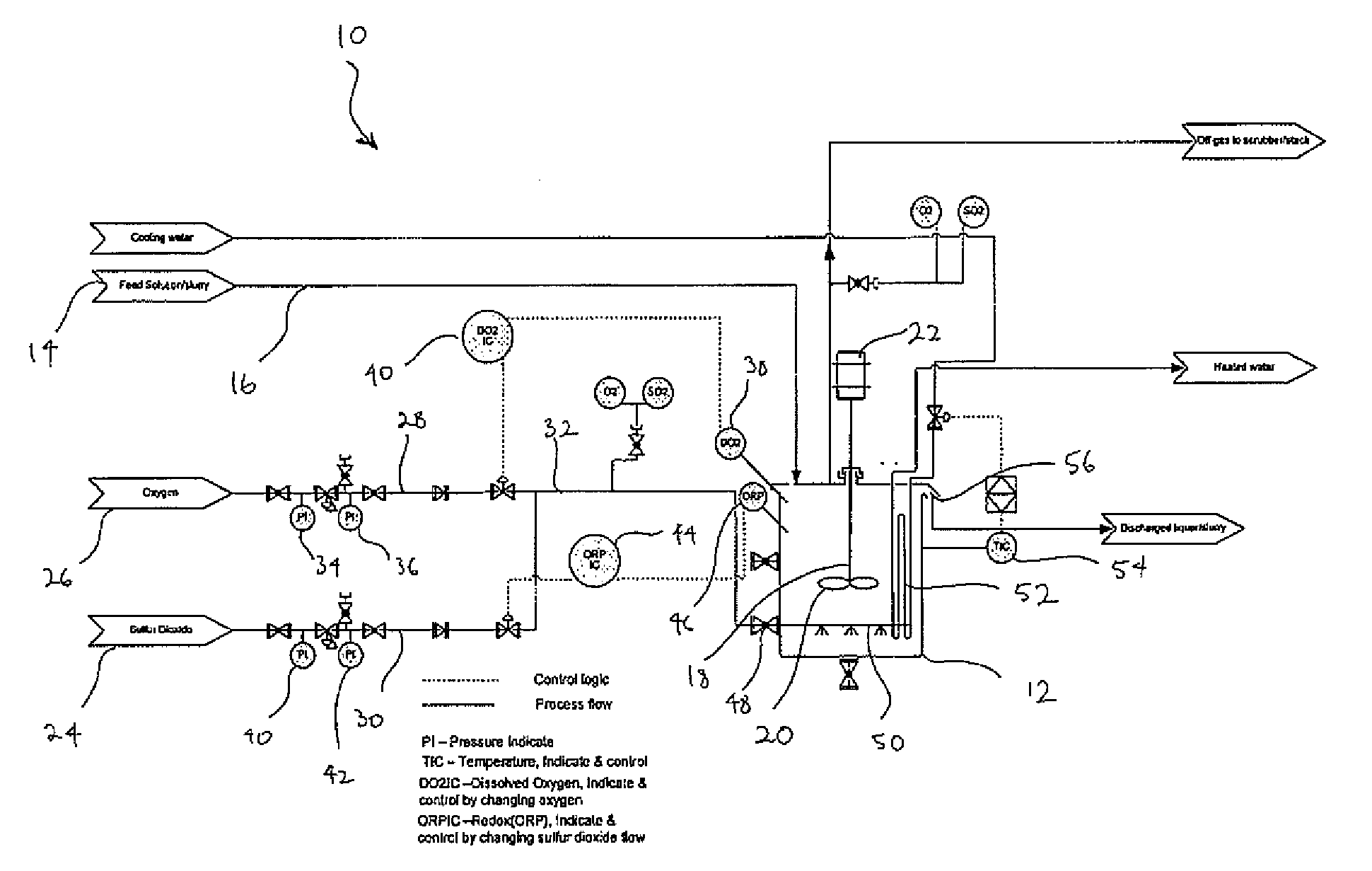
[0078]FIG. 1 is a schematic diagram of a plant 10 for use with the process of the present invention as exemplified in Examples 1 to 4. The plant 10 includes a reactor 12 into which a ferrous containing feed solution or slurry 14 is fed via a conduit 16. The reactor 12 includes a dissolved oxygen sensor 38, a redox sensor 46 and an agitator 18 comprising an impeller 20 driven by a motor 22. Sources of sulfur dioxide 24 and oxygen gas 26, respectively, are in fluid communication with the reactor 12 via gas inlet conduit 32. An oxygen conduit 28 extends from the oxygen source and a sulfur dioxide conduit 24 extends from the sulfur dioxide source. The two conduits are connected to inlet conduit 32. The oxygen conduit 28 includes oxygen pressure gauges 34 and 36 and means 40 for regulating the flow of oxygen through conduit 28 in response to readings from the DO sensor 38. The sulfur dioxide conduit 30 includes sulfur dioxide pressure gauges 40 and 42 and a means 44 for regulating the fl...

example 1

Solution 1: CLTO

[0097]Table 3 sets out the conditions of each oxidation test.

[0098]

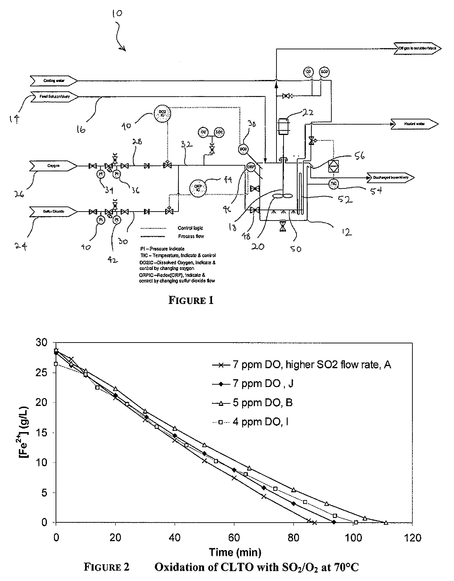
TABLE 3SO2 / O2 Oxidation of CLTO at 70° C.CalculatedFe2+Max. Fe2+oxidationIncreaseDissolvedoxidation rateAverage Fe2+Fe2+ oxidationrate belowinTestOxygenbased on SO2oxidation raterate to 4-6 g / L4-6 g / L Fe2+[H2SO4]ID(ppm)(g / L / h)(g / L / h)Fe2+ (g / L / h)(g / L / h)(g / L)SO2 A7~2720201611SO2 J7~2218191412SO2 B5~2216171215SO2 C5~171212na8SO2 I4.5~2416171317

[0099]The decrease in ferrous concentration from SO2 / O2 oxidation of CLTO at 70° C. and dissolved oxygen from 4-7 ppm is shown in FIG. 2.

[0100]The SO2 flowrate was equivalent to a maximum Fe2+ oxidation rate of 22-24 g / L / h, except for test SO2 A, where the SO2 flow rate was equivalent to a maximum Fe2+ oxidation rate of 27 g / L / h. The test at 4.5 ppm dissolved oxygen (DO) had a slightly lower initial ferrous concentration because oxygen was sparged through the liquor for five minutes before SO2 was added. It can be seen that maintaining an optimum value of dissolved...

example 2

Solution 2: CLTO+Raffinate

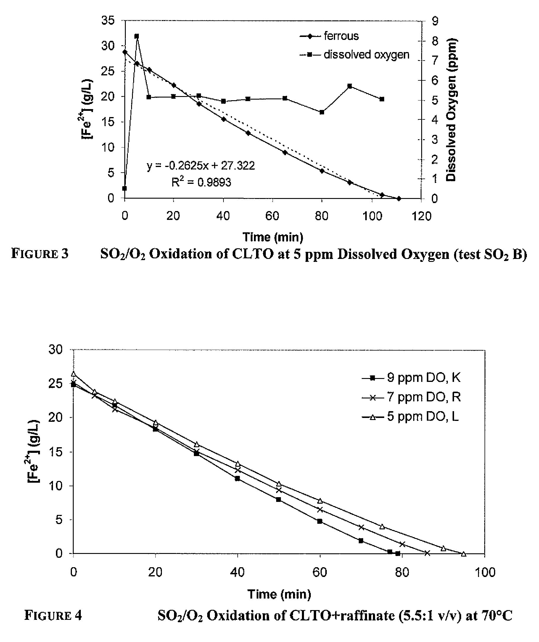
[0107]The decrease in ferrous concentration from SO2 / O2 oxidation of CLTO+raffinate (166 mL:30 mL or 5.5:1 / vv) at 70° C. is shown in FIG. 4. The SO2 feed rate was equivalent to a maximum Fe2+ oxidation rate of 22-23 g / L / h. The selectivity of ferrous oxidation reaction (1) over the acid generation reaction (3) decreased as the dissolved oxygen concentration decreased from 9 ppm to 5 ppm. Similarly to oxidation of CLTO, the ferrous oxidation rate decreased once the ferrous became depleted.

[0108]One test was run on CLTO:raffinate=1:1 (v / v) and the results are shown in FIG. 5. The SO2 feed rate was equivalent to a maximum Fe2+ oxidation rate of 17-24 g / L / h.

[0109]The ferrous oxidation rates are shown in Table 5.

[0110]

TABLE 4CalculatedFe2+Fe2+Max. Fe2+AverageoxidationoxidationoxidationFe2+rate torateIncreaseRatioDissolvedrate basedoxidation4-6 g / LbelowinCLTO:raffinateOxygenon SO2rateFe2+3-5 g / L[H2SO4](v / v)Test ID(ppm)(g / L / h)(g / L / h)(g / L / h)(g / L / h)(g / L)5.5:1SO2 K 92...


PUM

PropertyMeasurementUnit
temperatureaaaaaaaaaa
temperaturesaaaaaaaaaa

Abstract

A process for producing a ferric containing solution by the controlled oxidation of a ferrous containing solution, said process including providing a solution containing at least ferrous ions; treating the solution with one or more inlet gases containing sulfur dioxide and oxygen in order to oxidize said ferrous ions to ferric ions, wherein the delivery rate of the sulfur dioxide gas is oxidation rate limiting; and controlling the concentration of dissolved oxygen in said solution at an optimum value.

Description

[0001]This application claims priority to PCT Application Serial No. PCT / AU2009 / 001528 filed Nov. 24, 2009 published in English on May 27, 2010 as PCT WO 2010 / 057274; and to Australian Application No. 2008906086 filed Nov. 24, 2008, the entire contents of each are incorporated herein by reference.FIELD OF THE INVENTION[0002]This invention relates to a process for the controlled oxidation of a ferrous ion containing solution by treatment with sulfur dioxide and oxygen. In a particularly preferred embodiment, the invention relates to a process for leaching a metal value containing material which includes a step of controlled ferrous oxidation.BACKGROUND TO THE INVENTION[0003]Many hydrometallurgical processes generate large quantities of by product ferrous containing liquors. Examples of such processes include the recovery of uranium, copper, nickel, cobalt, zinc from their ores, ore concentrates or tailings. The ferrous ions represent a potential, inexpensive source of oxidant, which ...

Claims


Application Information

Patent Timeline
Patent Type & Authority Patents(United States)
IPC IPC(8): C22B15/00C22B3/44C22B3/04C22B60/02C22B5/00C22B3/00C22B3/06C22B3/02
CPCC22B23/0415C22B15/0067C22B3/44C22B60/0221C22B3/02C22B3/06Y02P10/20
Inventor RORKE, GARY, VERNON
Owner BHP BILLITON OLYMPIC DAM CORP
Learn More