High throughput multichannel reader and uses thereof

a multi-channel reader and high-throughput technology, applied in the field of high-content screening, can solve problems such as time-consuming, and achieve the effects of high content screening, high throughput, and high-content screening

Inactive Publication Date: 2015-01-20
TRUSTEES OF BOSTON UNIV
View PDF11 Cites 16 Cited by
  • Summary
  • Abstract
  • Description
  • Claims
  • Application Information

AI Technical Summary

Benefits of technology

[0014]The present invention generally relates to a high-throughput, high content screening (HCS) cytometry device based on image-analysis and sorting of particles (i.e. cells) based on particle (i.e. cell) phenotype. Thus, the present invention relates to a high-throughput, high content cytometry screening for phenotypic sorting of particles (i.e. cells) in a sample. The methods and compositions described herein combine desirable features of flow cytometry (FACS) and microscope-based high-content screening (HCS) to permit sorting of particles based on phenotypic characteristics such as asymmetry, shape, fluorescence or dye uptake / exclusion, and intracellular information (e.g., organelle shape and area). The present invention further permits intracellular localization assays to be performed, is highly sensitive to detection of rare cells, and can be used for time-synchronized sampling, which is not possible using FACS or HCS alone. The present invention is advantageous in that it allows identification and distinguishing of particles, e.g., cells based on gross morphological characteristics using line scan image analysis with a resolution which is high enough for distinguishing characteristics, but is of a resolution which does not significantly slow down the analysis, allowing for high throughput, high-content screening. One of the problems with 96- and 384-well plate-reader and plate-based image analysis systems is that they are static systems, requiring time for the focusing of beam for accurate and clear image capturing. In contrast, the present system, methods and apparatus performs image analysis on particles, e.g., cells, as they move or flow through a microchannel, therefore all particles, e.g., cells, are in focus allowing for rapid image capturing and accurate reading. Additionally, the present system, method and apparatus allows the particle, e.g., cell to be in the correct morphology, and reduces issues with cell aggregation which can be an issue with static 96- and 384-well plate-reader and plate-based image analysis systems.
[0024]Unlike FACS sorting, which can only sort cells from a single sample at one time and which requires cells from different samples to be sorted in sequential or subsequent FACS processing step, the present methods, apparatus, devices and composition allows for sorting of multiple different samples simultaneously, in real-time. As shown in FIG. 1, FIG. 2, and FIG. 18, in some embodiments, the present methods, apparatus, devices and composition allows for image analysis and subsequent sorting of 384 different samples simultaneously. In some embodiments, the multichannel architecture of the microfluidic device of the line-scan device as disclosed herein can be configured for line-image scanning of any number of different or unique samples. In some embodiments, the number of samples which can be line-scan imaged simultaneously can be about at least 16, or at least about at least 32, or at least about 96, or at least about 384, or at least about 500, or between about 500-1000, or multiples of 384, e.g., 768, or about 1152, or about 1536, or about 1536, or about 1920, or about 2304 etc. In some embodiments, the number of samples which are processed simultaneously is determined by one of ordinary skill in the art and can be determine in part, by the sample capacity of commercially available and conventional microwell plates (e.g., 16-well, 32-well, 96-well, 384-well plates etc). In another embodiment, one can scan a “sheet” of samples, and automate the process to prepare a new sheet of samples which can be simultaneously scanned or processed.
[0034]In some embodiments of the line-scan imager device, a large laser spot size is used (e.g., 30×100 microns, or 30×30 microns). Such a large laser spot size can be used for high throughput sorting of larger cells, for example, based on color ratio measurements without the need to resolve intracellular and internal cell structure, and can be used, for example, for a high sensitivity to identify rare cells. In some embodiments of line scan imaging device, a larger spot size will decrease the focus and clarity of the image, but can be useful to identify larger cells and / or rare cells, and / or to distinguish cells on the basis of light scattering, or the ratio of two or more different fluorescent markers. In some embodiments, the spatial resolution spot size can be determined by the user to identify a cell type of a specific size. For example, in some embodiments, the spatial resolution spot size can identify cells within the range of 1-50 μm, for example a spatial resolution spot size of 3.5 μm can be used to identify cells of about 10 μm, or a spatial resolution spot size of about 4-5 μm in can be used to identify a yeast cell of about 6 μm in diameter, or a spatial resolution spot size of about 1-3.5 μm can be used to identify cells about 1 μm, such as bacterial cells, or a spatial resolution spot size of about 3.5-5 μm can be used to identify cells about 50 μm such as heart cells and neurons. In some embodiments, the spatial resolution spot size can be adjusted accordingly to identify cells of about 3-15 μm in diameter, or between about 3-20 μm in diameter, or between about 1-10 μm in diameter, or cells about 20-50 μm in diameter, or cells greater than about 50 μm in diameter. In some embodiments, the spatial resolution spot size is adjusted so it allows enough resolution of the cell to see markers and / or internal structures of the cell and resolve details inside the cells yet being quick enough for quick image capture for high throughput analysis.
[0035]In some embodiments, the detector for capturing the line-scan images is configured to capture images of the particle, e.g., a cell as it flows through a microchannel. Surprisingly, as the particles are in the microchannel, each particle, e.g., cell is always in focus. Accordingly, no time is needed for focusing the image detector in the present system, which is a significant advantage over plate-reader image analysis systems, where cells in a plate microwell are not in focus and time is required for focusing the image detector for clear image capture. In some embodiments, the line-scan imaging device comprises a microfluidic device comprising a plurality of microchannels, wherein each microchannel of the plurality of microchannels is at least 50 μm wide in diameter, or at least 100 μm wide in diameter. In some embodiments, the diameter of each microchannel (e.g., depth) is between 30 and 300 μm (e.g., between 30-175, 30-150, 30-125, 30-100, 30-75, 30-50, 30-40, 50-75, 50-100, 50-125, 50-150, 50-175, 50-200, 75-200, 100-200, 125-200, 150-200 or 175-200 μm, or about 200-300 μm). In some embodiments, the diameter of the width of a microchannel is not greater than 300 μm wide in diameter. In some embodiments, the microchannel diameter is configured so that the detector does not need to focus to accurately and clearly capture the particles, e.g., cells as they flow the microchannel, or so that the detector need only a narrowly-adjusted focus for focusing on particles as they flow through the microchannel.
[0039]In some embodiments, each microchannel of the plurality of microchannels on the microfluidic device is configured for focusing, such as vertical hydrodynamic focusing. In some embodiments, vertical hydrodynamic focusing is achieved by using multiple crossing junctions of each microchannel to flow into a single analytical microchannel, where a single analytical microchannel is a scanning window or analytical portion of the microchannel. In some embodiments, the vertical hydrodynamic focusing locates cells to a zone of 20 μm or smaller (e.g., less than 18, less than 16, less than 14, less than 12, less than 10, less than 8, less than 6, less than 4, or less than 2 μm) in the direction of the optical focus. In some embodiments, vertical hydrodynamic focusing allows 4 μm to be detected with a 40× microscope objective.
[0044]In some embodiments, the comparison module is configured to analyze at least one line-scan image or a plurality of line scan images from each cell by comparison with a reference line scan image, and wherein if the line-scan image of the cell has substantially similar cell features, such as those in Table 1, as a reference line scan, the comparison module sends instructions to the microfluidic device to trigger or de-select switching of the piezoelectric microswitch in the microchannel in which the cell was scanned, enabling selection of the cell.

Problems solved by technology

One of the problems with 96- and 384-well plate-reader and plate-based image analysis systems is that they are static systems, requiring time for the focusing of beam for accurate and clear image capturing.

Method used


Image

  • High throughput multichannel reader and uses thereof
  • High throughput multichannel reader and uses thereof
  • High throughput multichannel reader and uses thereof

Examples


example 1

[0319]The design of a PMC differs from a FACS in (1) its need for a wide field of view detector (rather than a focused point detector), (2) its need for automation to support parallel sample transfer, (3) its differing needs for data processing and (4) the design of the microfluidic itself. The detector of the PMC is more complex than a FACS detector since the wide-field requirement mandates the use of a scanner and permits high-speed imaging.

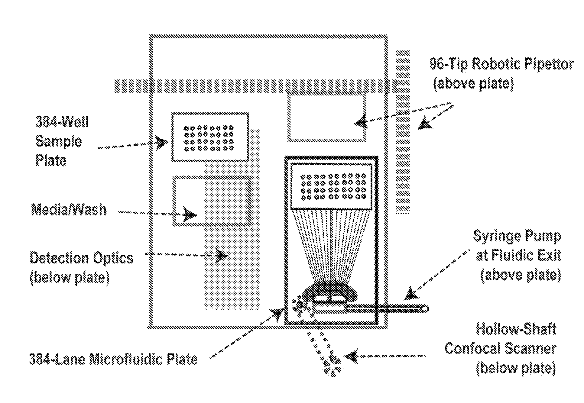
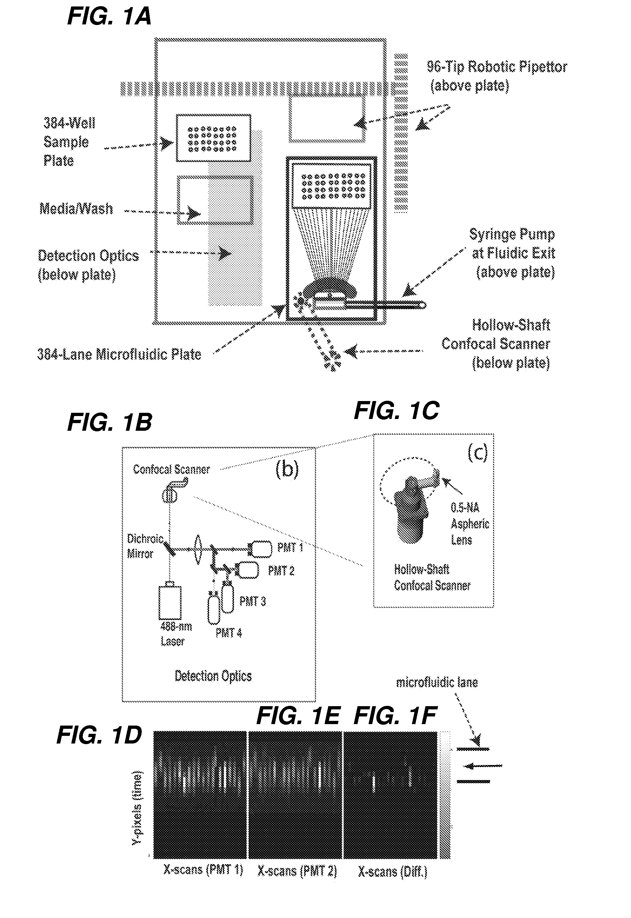
[0320]An exemplary automated PMC is shown herein in FIGS. 14 and 15. The microfluidic flow devices can be mounted on a top plate and can be serviced with a gantry robot combined with a sample elevator that handles 384-well microtiter plates. In one embodiment, the fluid handling is via an integrated 96-tip pipettor that permits automated maintenance of 384-well plates on a temperature controlled base. The sample deck can include positions for nutrient / wash trays that can also be accessed by the pipettor. As a result, live cell cultures can be s...

example 2

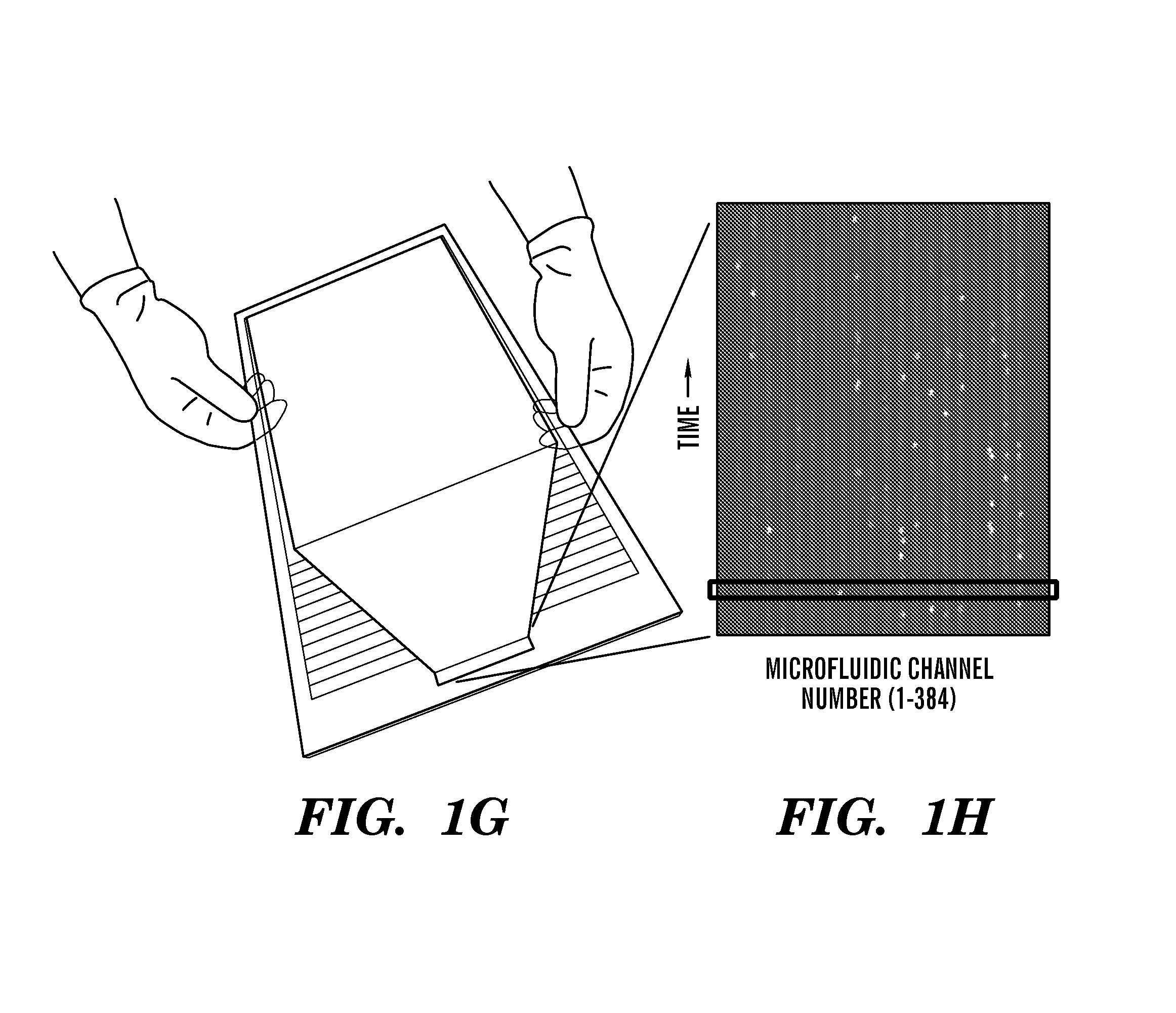
[0346]Algorithms that distinguish common protein location patterns in live and fixed cells using line-scan imaging. As the cells flow through the microdevice they cross over the detection window where a scanner is moving (e.g., every 1 / 100 of a second) and recording emitted fluorescence values every 1 μm across the 100-μm-wide channels. The fluorescence values recorded by the separate PMT's are then converted to 16-bit digital values and sent to the computer where they are assembled in computer memory as 10 line-scan images per cell (hardware below, Sect. Example 3).

[0347]Once the system has determined that a cell has just passed over the line-scanner, the pixel matrix that represents that cell is sent to a cell-typing algorithm. This assay-specific algorithm measures features about the cell using the florescence levels from PMT's individually and in comparison to each other (Table 1). Feature values from the algorithm will be calculated in microseconds, allowing the cell to be iden...

example 2.1

[0348]Classification by 1-D images: The inventors developed line-scan imaging algorithms for high-throughput, high-content image-based screening. Microscope-based (imaging) assays provide higher content than can be obtained by un-resolved total fluorescence, i.e., FACS. A key aspect for fluorescence localization assays will be fast image-analysis algorithms for binning of events. The economy of “line-scan” images (when compared to CCD images) is a computational advantage (Gonzales, R. C and Woods, R. E., Digital Image Processing, Prentice Hall, Upper Saddle N.J., 2002). The inventors prove the robustness of these “more economical” scans.

[0349]The classification ambiguity typical from 1-D imaging and as it relates to a protein-localization assay is illustrated for 2-colors in FIG. 6. By extracting only 1-D images, the feature set is greatly reduced with new classes of ambiguity relative to a conventional 2-D image; distinguishing features become asymmetries, profile shape factors, an...


PUM

PropertyMeasurementUnit
diameteraaaaaaaaaa
diameteraaaaaaaaaa
diameteraaaaaaaaaa

Abstract

The present invention relates generally to the field of high content screening of particles, e.g., cells in a flow cytometric system. In particular, the present invention relates to devices, methods and systems to obtain line-scan images of particles, e.g., cells, of a plurality of different samples simultaneously, where the line-scan images can be used to identify cells based on at least one of a variety of phenotypic characteristics such as shape, asymmetry, and intracellular information for cell sorting and selection. In some embodiments, the line-scan images are obtained as the particles, e.g., cells, in a plurality of different samples flow through a plurality of microchannels, reducing the need and time for focusing of the image detection system. In some embodiments, the laser spot size has a small spatial resolution for rapid capturing of images of cells. In some embodiments, the laser spot size has a larger spatial resolution for imaging of larger particles or cells, e.g., rare cells in a sample. In some embodiments, the devices, methods and systems are automated for a high-throughput, high content screening of particles such as cells in a plurality of samples.

Description

CROSS REFERENCE TO RELATED APPLICATION[0001]This application is a 35 U.S.C. §371 National Phase Entry Application of International Application No. PCT / US2010 / 047552 filed Sep. 1, 2010, which designates the U.S., and which claims benefit under 35 U.S.C. §119(e) of the U.S. provisional application No. 61 / 238,894 filed Sep. 1, 2009, the contents of which is incorporated herein in its entirety by reference.GOVERNMENT SUPPORT[0002]This invention was made with Government support under Grant No: HG001389 awarded by the National Institutes of Health. The Government has certain rights in the invention.FIELD OF THE INVENTION[0003]Embodiments of the invention are generally related to high content screening (HCS) in the field of flow cytometry. More particularly, embodiments of the invention are directed to coupling high content screening by flow cytometry with in line scan imaging in a parallel flow instrument for protein localization, and applications thereof, for a more efficient, less costl...

Claims


Application Information

Patent Timeline
Patent Type & Authority Patents(United States)
IPC IPC(8): G01N15/06G01N33/48G01N33/00G01N15/14
CPCG01N15/14Y10T436/11Y10T436/25Y10T436/2575
Inventor EHRLICH, DANIEL J.MCKENNA, BRIAN
Owner TRUSTEES OF BOSTON UNIV
Why Eureka
Try Eureka