Method of manufacturing a burner front face

a manufacturing method and burner technology, applied in the direction of gasifier mechanical details, combustion types, lighting and heating apparatus, etc., can solve problems such as effective heat dissipation, and achieve the effect of high mechanical strength and optimized heat dissipation

Active Publication Date: 2015-05-19
AIR PROD & CHEM INC
View PDF106 Cites 19 Cited by
  • Summary
  • Abstract
  • Description
  • Claims
  • Application Information

AI Technical Summary

Benefits of technology

[0009]It is an object of the present invention to provide a method of manufacturing a front face allowing a front face construction which balances optimized heat dissipation with a high mechanical strength.

Problems solved by technology

It has been found that a number of two or three concentric flow path sections result in effective heat dissipation with only limited pressure drop.

Method used


Image

  • Method of manufacturing a burner front face
  • Method of manufacturing a burner front face
  • Method of manufacturing a burner front face

Examples


Embodiment Construction

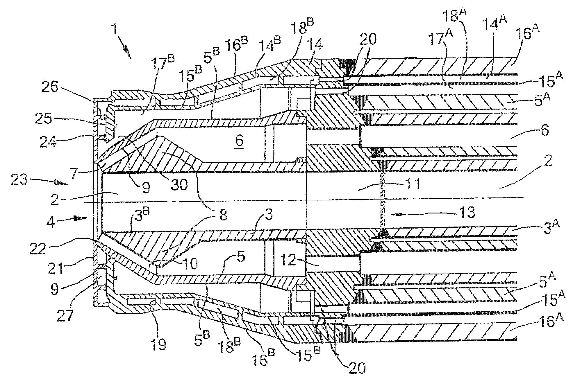
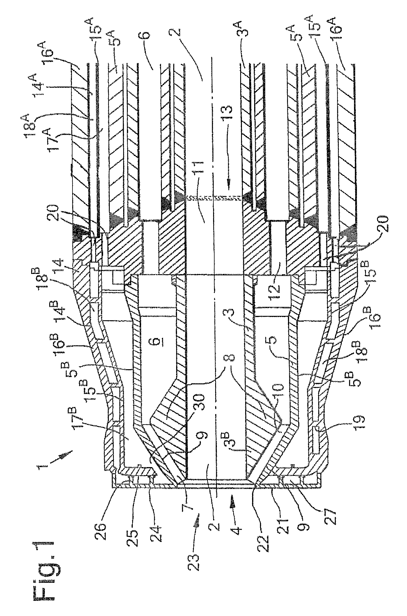
[0022]FIG. 1 shows in a longitudinal cross section a cylindrical burner 1 for the partial combustion of a carbonaceous fuel, such as pulverized coal carried on nitrogen or carbon dioxide gas. The burner 1 comprises a cylindrical central channel 2 defined by a cylindrical inner wall 3 disposed along longitudinal axis and having a discharge outlet 4 for supplying the fuel gas to a combustion zone. Concentrically arranged around the inner wall 3 is a cylindrical outer wall 5. In this particular embodiment, the inner and outer wall 3, 5 have double walled upstream parts 3A, 5A and single-walled downstream parts 3B, 5B. The inner and outer wall 3, 5 define an annular coaxial channel 6 for supplying an oxygen containing gas. The coaxial channel 6 has a discharge end 7 converging in the flow direction and forming an outlet for the oxygen-containing gas flow into the combustion zone.

[0023]The inner wall 3 has a constant inner diameter. The downstream wall part 3B has a conically expanded pa...


PUM

PropertyMeasurementUnit
wt. %aaaaaaaaaa
temperaturesaaaaaaaaaa
particle sizeaaaaaaaaaa

Abstract

The invention relates to a method of manufacturing a front face (21) for a burner (1), particularly for the gasification of solid carbonaceous materials by partial combustion. The front face (21) comprises a central aperture (23) corresponding to the discharge end of the burner, a front side wall (24) and a backside wall (25) spaced by one or more baffles (26) defining a coolant flow path with a coolant inlet (30) and a coolant outlet (31). The front side wall (24) and the one or more baffles (26) are made of a single piece of metal and the backside wall (25) is welded on the free top ends of the one or more baffles. The front face can for example be made of a steel according to UNS N07718.

Description

PRIORITY CLAIM[0001]The present application claims priority to European Patent Application 07113847.3 filed 6 Aug. 2007 and U.S. Provisional Patent Application 60 / 954,342 filed 7 Aug. 2007.FIELD OF THE INVENTION[0002]The invention relates to a method for manufacturing a front face for protecting the discharge end of a burner with two or more coaxial channels, the front face comprising a central aperture corresponding to the discharge end of the burner, a front side wall and a backside wall spaced by one or more baffles defining a coolant flow path with a first end provided with a coolant inlet and a second end having a coolant discharge outlet.BACKGROUND OF THE INVENTION[0003]Such a front face is particularly useful for protecting burners used for the partial combustion of carbonaceous fuels, such as finely divided solid fuel carried by a gas, e.g., pulverized coal carried by a carrier gas such as nitrogen gas or carbon dioxide, using an oxygen-containing gas, e.g., for producing pr...

Claims


Application Information

Patent Timeline
Patent Type & Authority Patents(United States)
IPC IPC(8): F23D1/00C01B3/36C10J3/50F23D11/36F23D14/22F23D14/78
CPCC10J2200/152F23D1/00F23D14/78F23D2214/00F23D2213/00C01B2203/0255C10J2200/09C10J3/506F23D11/36C01B3/363F23D14/22Y10T29/49348Y10T29/49345
Inventor BOER, ANNEVAN SCHIE, HENRICUS GIJSBERTUSSMIT, CORNELIS JACOBUS
Owner AIR PROD & CHEM INC
Why Eureka
Try Eureka