Check patentability & draft patents in minutes with Patsnap Eureka AI!

Reactor system, an absorbent and a process for reacting a feed

a technology of absorbent and feed, which is applied in the field of reactor system, absorbent and process for reacting a feed, can solve the problems of adversely affecting the performance of the catalyst, silver-based catalysts are especially metal or noble metal catalysts are generally susceptible to catalyst poisoning

Active Publication Date: 2015-09-29
SHELL USA INC
View PDF105 Cites 2 Cited by
  • Summary
  • Abstract
  • Description
  • Claims
  • Application Information

AI Technical Summary

Benefits of technology

The present invention provides a system for reacting feed components containing hydrocarbons, using an absorbent and a catalyst. The absorbent reduces impurities in the feed components, while the catalyst facilitates the desired reaction. The resulting reaction product can be a variety of compounds such as 1,2-diol, 1,2-diol ether, 1,2-carbonate, or alkanolamine. The system is efficient and effective in purifying the feed components and producing high-quality reaction products.

Problems solved by technology
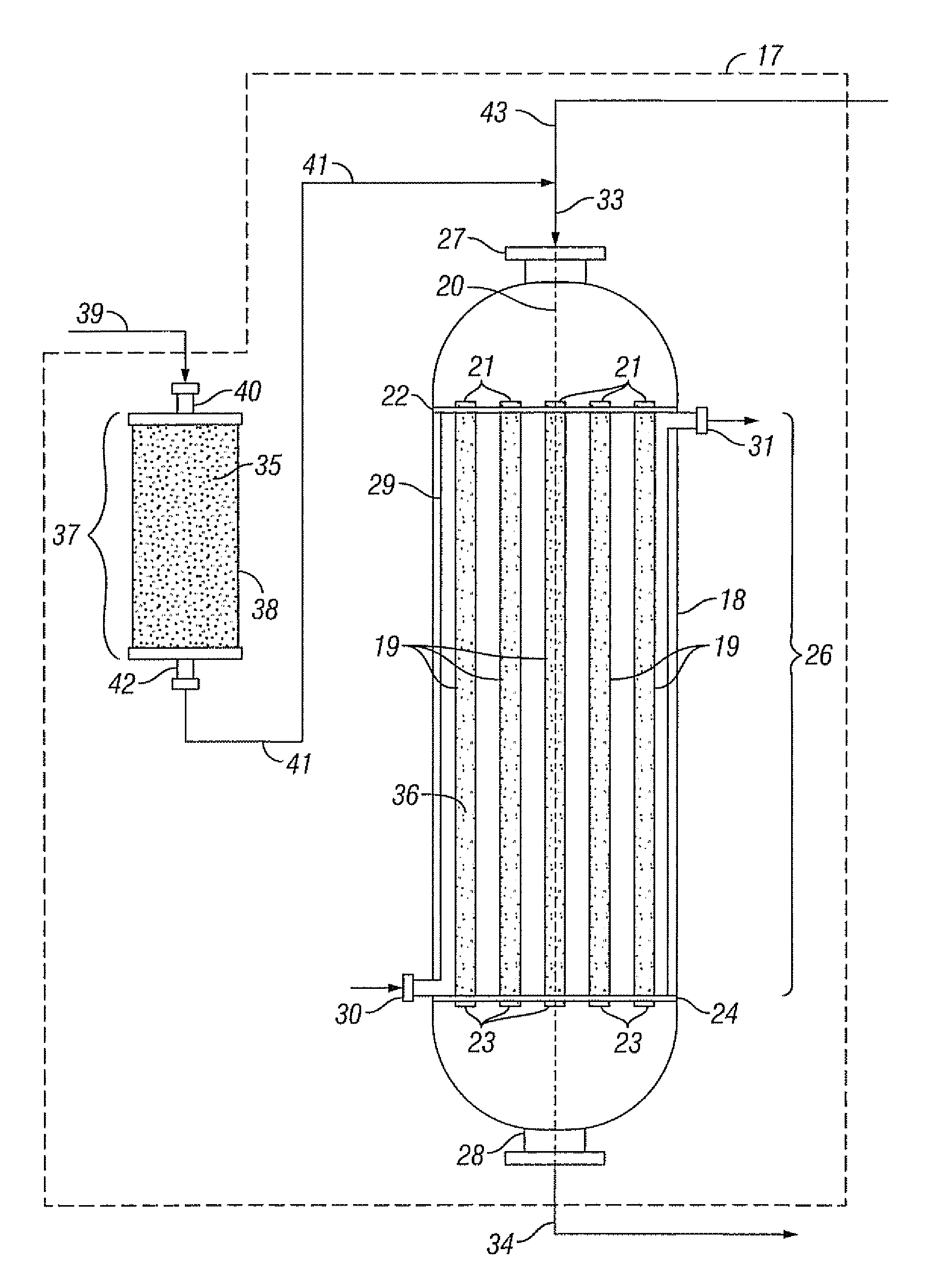
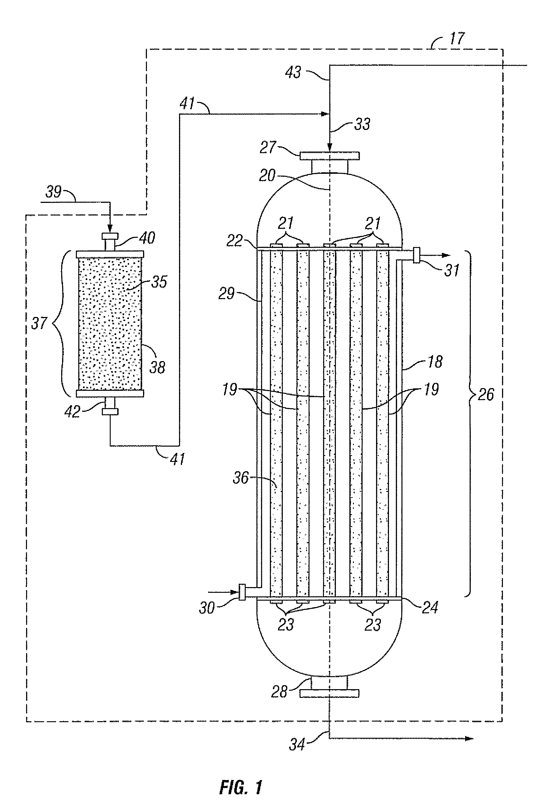
The low levels of impurities still remaining in the feedstream can act as catalyst poisons in the reaction process, adversely affecting the performance of the catalyst.
Metal or noble metal catalysts are generally susceptible to catalyst poisoning by these elements, for example many metals are known to form sulfides even if sulfur is present in the feedstream in quantities below the parts per million level.
These silver-based catalysts are especially susceptible to catalyst poisoning even at impurity amounts on the order of parts per billion levels.
The catalyst poisoning impacts the catalyst performance, in particular the selectivity or activity, and shortens the length of time the catalyst can remain in the reactor before having to exchange the poisoned catalyst with fresh catalyst.
However, placing an inert material upstream from the catalyst does not significantly reduce the amount of impurities present in the feed which can poison the catalyst.
Thus, not withstanding the improvements already achieved, there exists a desire for a reactor system and reaction process that further improves the performance of the catalyst, in particular the duration of time the catalyst remains in the reactor before exchanging with a fresh catalyst.

Method used


Image

  • Reactor system, an absorbent and a process for reacting a feed
  • Reactor system, an absorbent and a process for reacting a feed
  • Reactor system, an absorbent and a process for reacting a feed

Examples


example 1

Preparation of Stock Silver Solution

[0099]This example describes the preparation of a stock silver impregnation solution used in preparing Absorbent A in the Examples.

[0100]A silver-amine-oxalate stock solution was prepared by the following procedure:

[0101]In a 5-liter stainless steel beaker, 415 g of reagent-grade sodium hydroxide were dissolved in 2340 ml de-ionized water, and the temperature was adjusted to 50° C.

[0102]In a 4-liter stainless steel beaker, 1699 g high purity “Spectropure” silver nitrate was dissolved in 2100 ml de-ionized water, and the temperature was adjusted to 50° C.

[0103]The sodium hydroxide solution was added slowly to the silver nitrate solution, with stirring, while maintaining a solution temperature of 50° C. This mixture was stirred for 15 minutes. The pH of the solution was maintained at above 10 by the addition of sodium hydroxide solution as required.

[0104]Water was removed from the precipitate created in the mixing step and the conductivity of the wa...

example 2

Preparation of the Absorbent

Absorbent A:

[0106]Absorbent A was prepared by the following procedure: To 100 grams of stock silver solution of specific gravity 1.548 g / ml was added 1.0 g of sodium hydroxide dissolved in 20 g of water. A vessel containing 40 grams of Support A (see Table I below for a description of the gamma alumina trilobes) was evacuated to 20 mm Hg for 1 minute and the final impregnation solution was added to Support A while under vacuum, then the vacuum was released and the carrier allowed to contact the liquid for 3 minutes. The impregnated Support A was then centrifuged at 500 rpm for 2 minutes to remove excess liquid. Impregnated Support A was placed in a vibrating shaker and dried in air flowing at a rate of 16.2 Nl / h at 250° C. for 15 minutes producing Absorbent A.

[0107]The final composition of Absorbent A comprised 24.1% Ag as measured by digestion in nitric acid and silver titration and 260 mmole Na / kg absorbent, calculated on the basis of pore volume impreg...

example 3

Testing of the Absorbent

[0109]4 g of the crushed absorbent was loaded into a stainless steel U-shaped tube. The ends of the tube were connected to a gas flow system. The inlet gas pressure was 1550 kPa (absolute). The temperature of the absorbent was at ambient temperature (25° C.).

[0110]The gas mixture passed through the absorbent bed, in a “once-through” operation, during the entire five days of the test run and consisted of 10 ppmv dihydrogen sulfide (H2S), 10 ppmv carbonyl sulfide (COS), 10 ppmv ethanethiol (C2H5SH), 10 ppmv dimethylsulfide (CH3)2S, and the balance nitrogen. The flow rate of the gas mixture was 3.0 Nl / l·h. These levels of sulfur-containing impurities are much higher than experienced in commercial operations.

[0111]Six fractions of the absorbent bed were analyzed for total sulfur content by XRF (x-ray fluorescence) analysis. The results of the XRF analysis were as follows (from the inlet most fraction to the outlet most fraction): 0.85% w; 0.68% w; 0.25% w; 0.05% ...


PUM

PropertyMeasurementUnit
bed heightaaaaaaaaaa
internal diameteraaaaaaaaaa

Abstract

Reactor systems are provided that comprise a purification zone comprising an absorbent which comprises silver, an alkali or alkaline earth metal, and a support material having a surface area of more than 20 m2 / g, and a reaction zone comprising a catalyst, which reaction zone is positioned downstream from the purification zone.

Description

CROSS-REFERENCE TO RELATED APPLICATIONS[0001]This application is a divisional of U.S. patent application Ser. No. 12 / 865,010 filed Nov. 8, 2010, which is the National Stage of International Application No. PCT / US08 / 63722, filed May 15, 2008, which claims the benefit of U.S. Provisional Application Ser. No. 60 / 938,890, filed May 18, 2007, each of which is incorporated herein by reference.BACKGROUND OF THE INVENTION[0002]In industrial-scale chemical operations, components are used in the feedstream which typically contain low levels of impurities even after being subjected to a purification process. The low levels of impurities still remaining in the feedstream can act as catalyst poisons in the reaction process, adversely affecting the performance of the catalyst. Of particular concern are trace sulfur, halogen, phosphorous, arsenic and selenium impurities that may be present in the feedstream. Metal or noble metal catalysts are generally susceptible to catalyst poisoning by these el...

Claims


Application Information

Patent Timeline
Patent Type & Authority Patents(United States)
IPC IPC(8): B01D53/04B01J20/02B01J20/04B01J8/06B01J20/28B01D15/22B01J8/04
CPCB01D53/0423B01D15/22B01J8/0476B01J8/067B01J20/0233B01J20/041B01J20/28059B01D2253/306B01J2208/026B01J20/08B01J20/3204B01J20/3236B01D2253/25B01J20/28057
Inventor MATUSZ, MAREK
Owner SHELL USA INC
Features
  • R&D
  • Intellectual Property
  • Life Sciences
  • Materials
  • Tech Scout
  • Unparalleled Data Quality
  • Higher Quality Content
  • 60% Fewer Hallucinations
Learn More